Custom Search
|
|
  |
|
|
COMMON COMPONENTS Rocket launcher packages have several components that are common to all or most launcher packages. Any notable differences are pointed out in the following discussion.
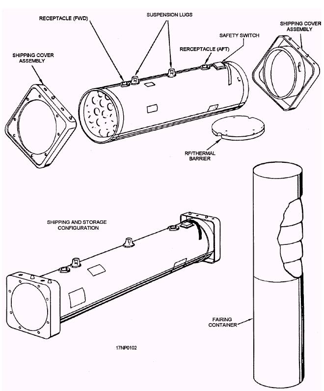
Figure 2-26.-Typical launcher shipping and storage configuration. Fakings Frangible fairings (fig. 2-27) are made of an impregnated molded fiber designed with a waffle- or grenade-type structure that shatters readily upon rocket impact or from a blast. The fairings fit flush with the outside surface of the center section and form an aerodynamically smooth joint. The forward fairing consists of a one-piece molded section that disintegrates on rocket impact. The tail fairing for the LAU-10 (series) (fig. 2-27, view A) is molded in two sections (nose and base), The rocket blast shatters the nose portion. The base section remains on the launcher and acts as a choke or funnel to direct debris away from the aircraft. The tail fairings for the LAU-61 and LAU-68 (series) are distinctively different in appearance (fig. 2-27, view B). They are made of aluminum and are open on both ends. They function in the same manner as the base section of the tail fairing for the LAU-10 (series). Fairings are not shipped with the rocket launcher packages. They must be ordered separately and are received in sets packaged in cylindrical-shaped cardboard fairing containers (fig. 2-26). Fairings are not used in all applications. You should review the specific aircraft tactical manual for any restrictions in their use. Breaker Switch A breaker switch is used on all rocket launchers. The breaker switch is a safe-arm device that prevents loaded rockets from firing. It is usually located on the top of the center section of the launcher between the aft end and the aft electrical receptacle. Figure 2-28 shows the various safe-arm devices currently in use.
Figure 2-27.-Rocket launcher airborne configurations.
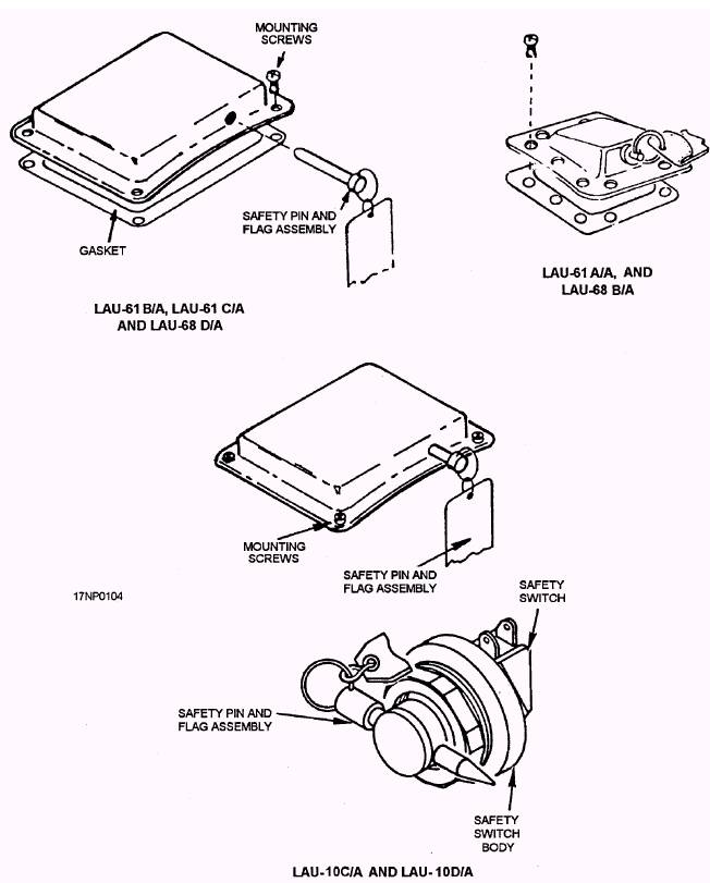
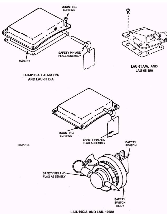
Figure 2-28.-Rocket launcher safe/arm devices.
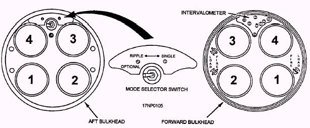
Figure 2-29.-Mode selector switch and intervalometer (5.0-inch launcher).
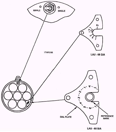
Figure 2-30.-Mode selector switch and intervalometer (LAU-68B/A and LAU-68D/A).
Figure 2-28.-Rocket launcher safe/arm devices. With the detent pin installed in the breaker switch, the electrical system is grounded in the safe position, and the rockets won't fire. The detent pin has a REMOVE BEFORE FLIGHT red streamer attached. Pull the pin immediately before the aircraft takes off and install it immediately after the aircraft lands. Install the detent pin in the breaker switch before loading the launcher with rocket motors. Keep the detent pin installed, except during actual flight, until the launcher is downloaded and/or verified as being empty. |
|
|
|