Custom Search
|
|
  |
|
|
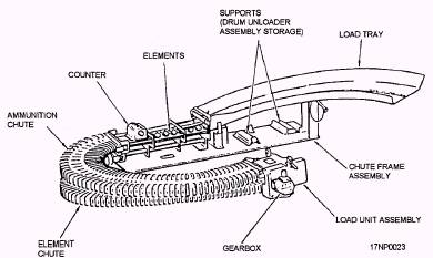
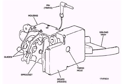
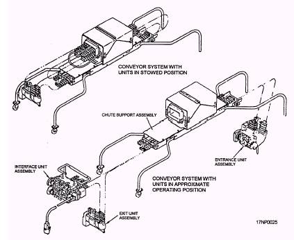
OUTER DRUM.- The outer drum is a storage container for ammunition, and it provides a housing for the inner drum. There is a rounds-remaining indicator window so you can determine the number of rounds remaining in the drum. The drum partitions, mounted longitudinally within the outer drum to hold the rounds in place, hold the rounds radially around the outer drum with their bases in an outward direction. INNER DRUM.- The inner drum is a welded assembly with a mounting ring at each end. There are sheet metal leaves welded to the outer surface of the core that form a double-lead helix. When the inner drum is rotated, it moves the rounds along the drum partitions from the entrance end to the exit end of the drum. SCOOP DISK ASSEMBLIES.- A scoop disk assembly is mounted on each end of the inner drum. There are three rails on the scoop disk assemblies, forming a continuation of the inner drum helix. Also, two sets of gear-driven sprockets and scoop extensions are located on the scoop disks 180 degrees apart. These sprockets and scoop extensions transfer the rounds from the entrance cover to the outer drum partitions and from the outer drum partitions to the exit cover. The entrance scoop disk has two pins that hold the scoop extensions closed when they are activated by a cam in the outer drum. This prevents feeding rounds into the empty space where the drum partitions cannot control the rounds. DRUM COVER ASSEMBLIES.- A drum cover assembly is mounted on each end of the outer drum. The drum cover assemblies accept rounds from the entrance unit, load units, or from the scoop disk assembly. It then places the rounds into the scoop disk assembly (entrance end) or exit unit, respectively. The retainer partitions on the retainer gear maintain control of the rounds between the scoop disk assemblies and the entrance or exit units. A spring-loaded timing pin on each drum cover is used to index the drum during installation of the entrance and exit units. The exit drum cover assembly also contains brackets for mounting a drive assembly. The drum loader assembly (fig. 7-8) is used to load the transporter with unlinked ammunition. The drum loader assembly places the unlinked rounds into the conveyor elements, which carry the rounds to the load unit assembly. The load unit assembly removes the rounds from the elements and places them into the retainer partitions in the entrance drum cover. You can time the load unit assembly by inserting a pin through the cover, through a hole in one of the gears, and into a hole in the housing. The drum loader consists of a load tray (onto which the rounds are placed), a belt of elements, two chutes (which control the rounds and elements when they are between the tray and the load unit), and a load unit assembly. The load unit assembly contains two gear-driven sprocket assemblies that transfer the rounds from the belt of elements to the drum cover partitions and a gearbox that drives the drum loader assembly. The gearbox can be driven by a l/2-inch drive hand crank, making it easier to transport the rounds. A resettable counter indicates the number of rounds that have been loaded into the transporter. Drum Unload Assembly The drum unload assembly (fig. 7-9) removes rounds and/or spent cases from the transporter and separates them from each other. The drum unload assembly contains a gear-driven sprocket that removes the rounds/spent cases from the drum exit cover and places them on a tray. The tray has a hole that lets spent cases drop through while the rounds must travel the length of the tray. You can time the drum unload assembly by inserting a pin through the cover, through a hole in one of the gears, and into a hole in the housing. The conveyor system (fig. 7-10) transports rounds from the transporter to the aircraft system. It simultaneously transports spent cases and cleared rounds from the aircraft system to the transporter. The conveyor system is mounted on the top of the transporter. It consists of a chute support assembly, three ammunition chutes, two element chutes, an exit unit assembly, an interface unit assembly, an entrance unit assembly, and a drum drive assembly that is driven by a flexible drive shaft. CHUTE SUPPORT ASSEMBLY.- The chute support assembly is a rigid structure that supports other units. It also provides stowage for other units when they aren't in use. A portion of the chute that is required for the control of spent cases and elements is a rigid wire-form chute. This chute is part of the chute support assembly. Casters are provided on one end of the chute support assembly to aid in moving the assembly when it is not mounted on a transporter. CHUTES.- The ammunition and element chutes control the elements and rounds or spent cases when the system is operating. The chutes are flexible enough to permit interconnection of the various units.
Figure 7-8.-Drum loader. 7-8
Figure 7-9.\Drum unloader.
Figure 7-10.\Conveyor system. EXIT UNIT ASSEMBLY.- The exit unit assembly removes rounds from the transporter and places them into the elements. Two gear-driven sprocket assemblies are used to transfer the rounds from the transporter to the elements. You can time the exit unit assembly by inserting a pin through the cover, through a hole in one of the gears, and into a hole in the housing. INTERFACE UNIT ASSEMBLY.- The interface unit assembly transfers the rounds coming from the exit unit assembly to the aircraft system and the spent cases coming from the aircraft system to the elements going to the entrance unit. A bypass mode of operation permits the rounds to be cycled through the transporter/conveyor system without an interchange of rounds at the interface unit. The interface unit assembly has a gearbox drive that drives the transporter/conveyor system at the speed required for correct hand-off between the interface unit and the aircraft system. The three gear-driven sprockets control the elements and rounds as they pass through the interface unit assembly. A resettable counter indicates the number of rounds that have been loaded into the aircraft system. ENTRANCE UNIT ASSEMBLY.- The entrance unit assembly removes spent cases/cleared rounds from the elements and places them into the transporter. There are three gear-driven sprockets that control the elements and spent cases as they pass through the entrance unit assembly. A counter indicates the total number of elements that have been cycled. DRUM DRIVE ASSEMBLY AND FLEXIBLE DRIVE SHAFT.- The drum drive assembly is mounted on the exit end of the transporter and drives the transporter drum. The drive power is transmitted from the interface unit to the drum drive assembly by the flexible drive shaft. OPERATION Operation of the LALS is divided into three modes: loading/downloading the transporter; loading/ downloading aircraft gun systems; and bypass. |
 
|
|
|