Custom Search
|
|
  |
|
|
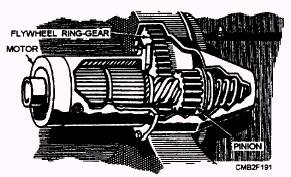
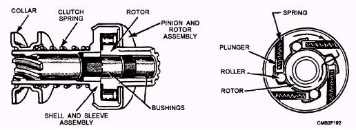
The pinion gear is a small gear on the armature shaft that engages the ring gear on the flywheel. Most starter pinion gears are made as part of a pinion drive mechanism. The pinion drive mechanism slides over one end of the starter armature shaft. The pinion drive mechanism found on starting motors that you will encounter are of three designs- Bendix drive, overrunning clutch, and Dyer drive. The BENDIX DRIVE (fig. 2-38) relies on the principle of inertia to cause the pinion gear to mesh with the ring gear. When the starting motor is not operating, the pinion gear is out of mesh and entirely away from the ring gear. When the ignition switch is engaged, the total battery voltage is applied to the starting motor, and the armature immediately starts to rotate at high speed. The pinion, being weighted on one side and having internal screw threads, does not rotate immediately with the shaft but because of inertia, runs forward on the revolving threaded sleeve until it engages with the ring gear. If the teeth of the pinion and ring gear do not engage, the drive spring allows the pinion to revolve and forces the pinion to mesh with the ring gear. When the pinion gear is engaged fully with the ring gear, the pinion is then driven by the starter through the compressed drive spring and cranks the engine. The drive spring acts as a cushion while the engine is being cranked against compression. It also breaks the severity of the shock on the teeth when the gears engage and when the engine kicks back due to ignition. When the engine starts and runs on its own power, the ring gear drives the pinion at a higher speed than does the starter. This action causes the pinion to turn in the opposite direction on the threaded sleeve and automatically disengages from the ring gear. This prevents the engine from driving the starter. The OVERRUNNING CLUTCH (fig. 2-39) provides positive meshing and demeshing of the starter motor pinion gear and the ring gear. The starting motor armature shaft drives the shell and sleeve assembly of the clutch. The rotor assembly is connected to the pinion gear which meshes with the engine ring gear. Spring-loaded steel rollers are located in tapered notches between the shell and the rotor. The springs
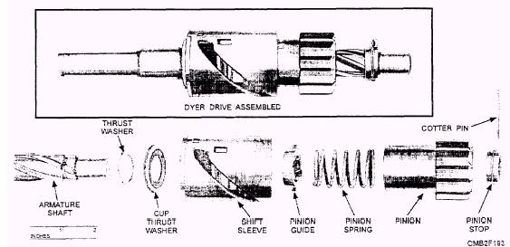
Figure 2-38.- Starting motor with a Bendix drive. Figure 2-39.- Typical overrunning clutch. and plungers hold the rollers in position in the tapered notches. When the armature shaft turns, the rollers are jammed between the notched surfaces, forcing the inner and outer members of the assembly to rotate as a unit and crank the engine. After the engine is started, the ring gear rotates faster than the pinion gear, thus tending to work the rollers back against the plungers, and thereby causing an overrunning action. This action prevents excessive speed of the starting motor. When the starting motor is released, the collar and spring assembly pulls the pinion out of mesh with the ring gear. The DYER DRIVE (fig. 2-40) provides complete and positive meshing of the drive pinion and ring gear before the starting motor is energized. It combines principles of both the Bendix and overrunning clutch drives and is commonly used on heavy-duty engines. A starter solenoid is used to make the electrical connection between the battery and the starting motor. The starter solenoid is an electromagnetic switch; it is similar to other relays but is capable of handling higher current levels. A starter solenoid, depending on the design of the starting motor, has the following functions: Closes battery-to-starter circuit. Bypass resistance wire in the ignition circuit.
Figure 2-40.- Dyer drive. In operation, the solenoid is actuated when the ignition switch is turned or when the starter button is depressed. The action causes current to flow through the solenoid (causing a magnetic attraction of the plunger) to ground. The movement of the plunger causes the shift lever to engage the pinion with the ring gear. After the pinion is engaged, further travel of the plunger causes the contacts inside the solenoid to close and directly connects the battery to the starter. If cranking continues after the control circuit is broken, it is most likely to be caused by either shorted solenoid windings or by binding of the plunger in the solenoid. Low voltage from the battery is often the cause of the starter making a clicking sound. When this occurs, check all starting circuit connections for cleanliness and tightness. |
 |
|
|