Custom Search
|
|
  |
|
|
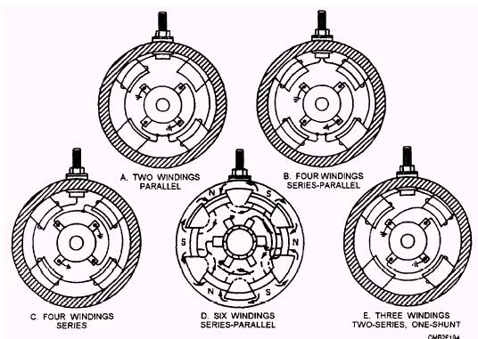
The field coil (winding) is a stationary set of windings that creates a strong magnetic field around the motor armature. When current flows through the winding, the magnetic field between the pole shoes becomes very large. Acting against the magnetic field created by the armature, this action spins the motor with extra power. Field windings vary according to the application of the starter motor. The most popular configurations are as follows (fig. 2-41): TWO WINDINGS, PARALLEL- The wiring of the two field coils in parallel will increase their strength because they receive full voltage. Note that two additional pole shoes are used. Though they have no windings, their presence will further strengthen the magnetic field. FOUR WINDINGS, SERIES-PARALLEL- The wiring of four field coils in a series-parallel combination creates a stronger magnetic field than the two field coil configuration. FOUR WINDINGS, SERIES- The wiring of four field coils in series provides a large amount of low-speed torque, which is desirable for automotive starting motors. However, series-wound motors can build up excessive speed if
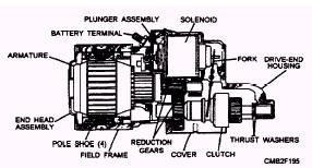
Figure 2-41.- Field winding configurations. SIX WINDINGS, SERIES-PARALLEL- THREE WINDINGS, TWO SERIES, ONE SHUNT- The use of one filled coil that is shunted to ground with a series-wound motor controls motor speed. Because the shunt coil is not affected by speed, it will draw a steady heavy current, effectively limiting speed. DRIVE END FRAME.- The drive end frame is designed to protect the drive pinion from damage and to support the armature shaft. The drive end frame of the starter contains a bushing to prevent wear between the armature shaft and drive end frame. Types of Starting Motors DIRECT DRIVE STARTERS.- Direct drive starters make use of a pinion gear on the armature shaft of the starting motor. This gear meshes with teeth on the ring gear. There are between 10 to 16 teeth on the ring gear for every one on the pinion gear. Therefore, the starting motor revolves 10 to 16 times for every revolution of the ring gear. In operation, the starting motor armature revolves at a rate of 2,000 to 3,000 revolutions per minute, thus turning the engine crankshaft at speeds up to 200 revolutions per minute. DOUBLE REDUCTION STARTER.- The double reduction starter makes use of gear reduction within the starter and the reduction between the drive pinion and the ring gear. The gear reduction drive head is used on heavy-duty equipment. Figure 2-42 shows a typical gear reduction starter. The gear on the armature shaft does not mesh directly with the teeth on the ring gear, but with an intermediate gear which drives the driving pinion. This action provides additional breakaway, or starting torque, and greater cranking power. The armature of a starting motor with a gear reduction drive head may rotate as many as 40 revolutions for every revolution of the engine flywheel.
Figure 2-42.- Gear reduction starter. |
 
|
|
|