 |
||
|
|
||
| |||||||||||||||
|
|
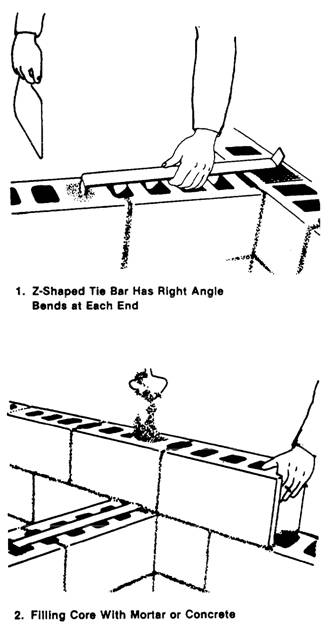
WALLS Walls are differentiated into two types: load bearing and nonload bearing. Load-bearing walls not only separate spaces, but also provide structural support for whatever is above them. Nonload bearing walls function solely as partitions between spaces. Load-bearing Walls Do not join intersecting concrete block loadbearing walls with a masonry bond, except at the corners. Instead, terminate one wall at the face of the second wall with a control joint. Then, tie the intersecting walls together with Z-shaped metal tie bars 1/4-by-1/4-by-28 inches in size, having 2-inch right-angle bends on each end (figure 8-22, view 1).
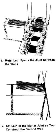
Figure 8-22.-Tying intersecting bearing walls. Space the tie bars no more than 4 feet apart vertically and place pieces of metal lath under the block cores that will contain the tie bars ends (figure 8-18, view 1). Embed the right-angle bends in the cores by filling them with mortar or concrete (figure 8-22, view 2). Nonload-bearing Walls To join intersecting nonload-bearing block walls, terminate one wall at the face of the second with a control joint. Then, place strips of metal lath of
Figure 8-23.-Tying intersecting nonbearing walls.
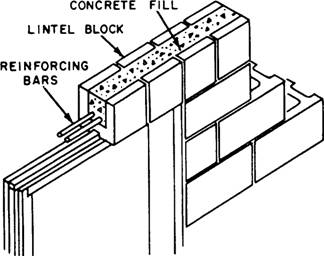
Figure 8-24.-Lintel made from blocks. 1/4-inch mesh galvanized hardware cloth across the joint between the two walls (figure 8-23, view 1) in alternate courses. Insert one-half of the metal stops into one wall as you build it, and then tie the other halves into the mortar joints as you lay the second wall (view 2).
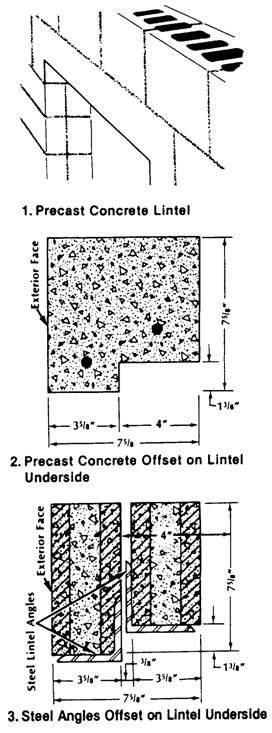
Figure 8-25.-Installing precast concrete lintels without end with steel angles.
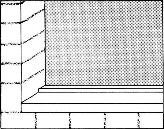
Figure 8-26.-Installed precast concrete sills. |
|
Privacy Statement - Press Release - Copyright Information. - Contact Us - Support Integrated Publishing |