 |
||
|
|
||
| |||||||||||||||
|
|
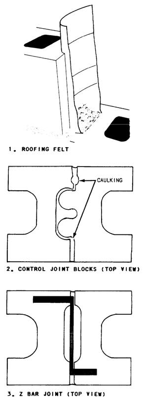
CONTROL JOINTS Control joints (figure 8-19) are continuous vertical joints that permit a masonry wall to move slightly under unusual stress without cracking. There are a number of types of control joints built into a concrete masonry wall. The most preferred control joint is the Michigan type made with roofing felt. A strip of felt is curled into the end core, covering the end of the block on one side of the joint (figure 8-20, view 1). As the other side of the joint is laid, the core is filled with mortar. The filling bonds to one block, but the paper prevents bond to the block on the other side of the control joint. View 2 of figure 8-20 shows the tongue-andgroove type of control joint. The special units are manufactured in sets consisting of full and half blocks. The tongue of one unit fits into the groove of another unit or into the open end of a regular flanged stretcher. The units are laid in mortar exactly the same as any other masonry units, including mortar in the head joint. Part of the mortar is allowed to remain in the vertical joint to form a backing against which the caulking can be packed. View 3 shows a control joint that may be built with regular full- and half-length stretcher blocks with a Z-shaped bar across the joint or a 10- or 12-inch pencil rod (1/4-inch smooth bar) across each face shell. If a pencil rod is used, it must be greased on one side of the joint to prevent bond. These rods should be placed every other course. Lay up control joints in mortar just as any other joint. However, if
Figure 8-20.-Making control joints.
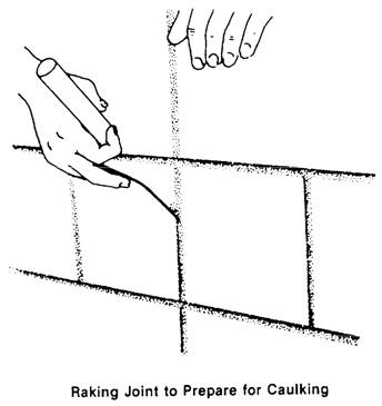
Figure 8-21.-Making a control joint. they are exposed to either the weather or to view, caulk them as well. After the mortar is stiff, rake it out to a depth of about 3/4-inch to make a recess for the caulking compound. Use a thin, flat caulking trowel to force the compound into the joint (figure 8-21). The location of control joints is established by the architectural engineer and should be noted in the plans and specifications. |
|
Privacy Statement - Press Release - Copyright Information. - Contact Us - Support Integrated Publishing |