 |
||
|
|
||
| |||||||||||||||
|
|
Location for Reinforcing Steel The proper location for reinforcing bars is given on the drawings. To ensure that the structure can withstand the loads it must carry, place the steel in exactly the position shown. Secure the bars in position so that they will not move when the concrete is placed. This can be accomplished by using the reinforcing bar supports shown in figures 7-22, 7-23, and 7-24. Footings and other principal structural members that are against the ground should have at least 3
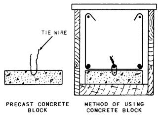
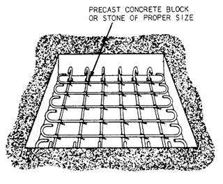
Figure 7-23.-Precast concrete block used for reinforcing steel support.
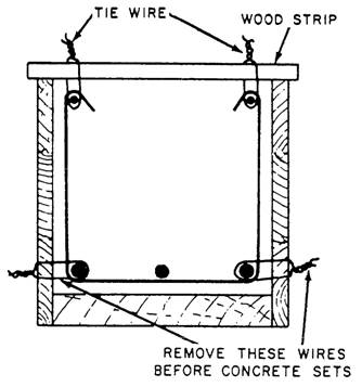
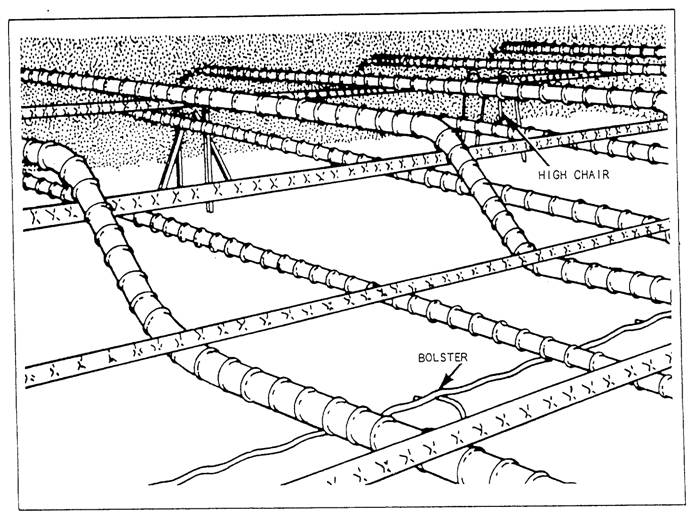
Figure 7-24: Beam-reinforcing steel hung in place. inches of concrete between steel and ground. If the concrete surface is to be in contact with the ground or exposed to the weather after removal of the forms, the protective covering of concrete over the steel should be 2 inches for bars larger than No. 5 and 1 1/2 inches for No. 5 or smaller. The protective covering maybe reduced to 1 1/2 inches for beams and columns and 3/4 inch for slabs and interior wall surfaces, but it should be 2 inches for all exterior wall surfaces. The clear distance between parallel bars in beams, footings, walls, and floor slabs should be a minimum of 1 inch, or one and one-third times the largest size aggregate particle in the concrete. In columns, the clear distance between parallel bars should be a minimum of one and one-half times the bar diameter, one and one-half times the maximum size of the coarse aggregate, or not less than 1 1/2 inches. The support for reinforcing steel in floor slabs is shown in figure 7-25. The height of the slab bolster is determined by the concrete protective cover required. Concrete blocks made of sand-cement mortar can be used in place of the slab bolster. Wood blocks should never be used for this purpose if there is any possibility the concrete might become wet and if the construction is of a permanent type. Bar chairs, like those shown in figure 7-25, are available from commercial sources in heights up to 6 inches. If a height greater than 6 inches is required, make the
Figure 7-25.-Reinforcing steel for a floor slab. chair of No. 0 soft annealed iron wire. Tie the bars together at frequent intervals with a snap tie to hold them firmly in position. Steel for column ties can be assembled into cages by laying the vertical bars for one side of the column horizontally across a couple of sawhorses. The proper number of ties is slipped over the bars, the remaining vertical bars are added, and then the ties are spaced out as required by the placing plans. A sufficient number of intersections are wired together to make the assembly rigid. This allows it to be hoisted and set as a unit. After the column form is raised, it is tied to the dowels or reinforcing steel carried up from below. This holds it firmly in position at the base. The column form is erected, and the reinforcing steel is tied to the column form at 5-foot intervals, as shown in figure 7-26.
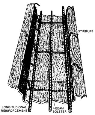
Figure 7-26.-Securing a column with reinforcing steel against displacement. The use of metal supports to hold beamreinforcing steel in position is shown in figure 7-27. Note the position of the beam bolster. The stirrups are tied to the main reinforcing steel with a snap tie. Whenever possible, you should assemble the stirrups and main reinforcing steel outside the form and then place the assembled unit in position. Wood blocks should be substituted for the metal supports only if there is no possibility of the concrete becoming wet or if the construction is known to be temporary. Precast concrete blocks, as shown in figure 7-23, may be substituted for metal supports or, if none of the types of bar supports described above seem suitable, the method shown in figure 7-24 may be used. Placement of steel in walls is the same as for columns except that the steel is erected in place and not preassembled. Horizontal steel is tied to vertical steel at least three times in any bar length. Steel in place in a wall is shown in figure 7-28. The wood block is removed when the form has been filled up to the level of the block. For high walls, ties in between the top and bottom should be used. Steel is placed in footings very much as it is placed in floor slabs. Stones, rather than steel supports, may be used to support the steel at the
Figure 7-27.-Beam-reinforcing steel supported on beam bolsters.
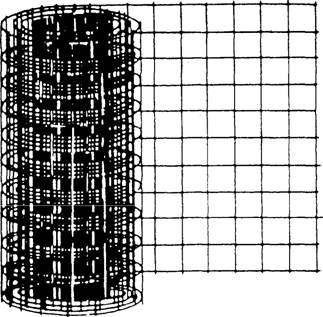
Figure 7-28.-Steel in place in a wall. proper distance above the subgrade. Steel mats are generally preassembled and placed in small footings after the forms have been set. A typical arrangement is shown in figure 7-29. Steel mats in large footings are generally constructed in place. Welded wire fabric (figure 7-30) is also used as limited reinforcement for concrete footings, walls, and slabs, but its primary use is to control crack widths due to temperature changes. Form construction for each job has its peculiarities. However, certain natural conditions prevail in all situations. Wet concrete always develops hydrostatic pressure and strain on forms. Therefore, all stakes,
Figure 7-29.-Steel in place in a footing.
Figure 7-30.-Welded wire mesh fabric. braces, walers, ties, and shebolts should be properly secured before placing concrete. Splicing Reinforcing Bar Because rebar is available only in certain lengths, it must be spliced together for longer runs. Where splices are not dimensioned on the drawings, the bars should be lapped not less than 30 times the bar diameter, or not less than 12 inches. The stress in a tension bar can be transmitted through the concrete and into another adjoining bar by a lap splice of proper length. The lap is expressed as the number of bar diameters. If the bar is No. 2, make the lap at least 12 inches. Tie the bars together with a snap tie (figure 7-31). |
|
Privacy Statement - Press Release - Copyright Information. - Contact Us - Support Integrated Publishing |