 |
||
|
|
||
| |||||||||||||||
|
|
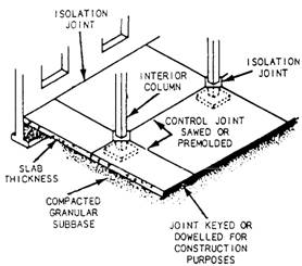
CONCRETE CONSTRUCTION JOINTS LEARNING OBJECTIVE: Upon completing this section, you should be able to determine the location of construction joints. Concrete structures are subjected to a variety of stresses. These stresses are the result of shrinkage and differential movement. Shrinkage occurs during hydration, and differential movement is caused by temperature changes and different loading conditions. These stresses can cause cracking, spalling, and scaling of concrete surfaces and, in extreme cases, can result in failure of the structure. TYPES OF JOINTS Stresses in concrete can be controlled by the proper placement of joints in the structure. We'll discuss three basic types of joints: isolation joints, control joints, and construction joints. Isolation Joints Isolation joints are used to separate (isolate) adjacent structural members. An example is the joint that separates the floor slab from a column. An isolation joint allows for differential movement in the vertical plane due to loading conditions or uneven settlement. Isolation joints are sometimes called expansion or contraction joints. In this context, they allow for differential movement as a result of temperature changes (as in two adjacent slabs). All isolation joints (expansion or contraction) extend completely through the member and have no load
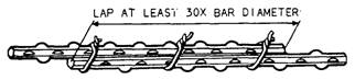
Figure 7-31.-Bars spliced by lapping.
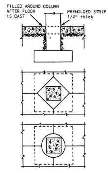
Figure 7-32.-Typical isolation and control joints. transfer devices built into them. Examples of these are shown in figures 7-32, 7-33, and 7-34. Control Joints Movement in the plane of a concrete slab is caused by drying shrinkage and thermal contraction. Some shrinkage is expected and can be tolerated, depending on the design and exposure of the particular structural elements. In a slab, shrinkage occurs more rapidly at the exposed surfaces and causes upward curling at the edges. If the slab is
Figure 7-33.-Isolation joints at columns and walls.
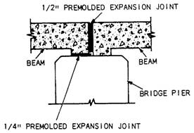
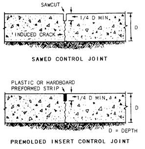
Figure 7-34.-Expansion/contraction joint for a bridge. restrained from curling, cracking will occur wherever the restraint imposes stress greater than the tensile strength. Control joints (figure 7-35) are cut into the concrete slab to create a plane of weakness, which forces cracking (if it happens) to occur at a designated place rather than randomly. These joints run in both directions at right angles to each other. Control joints in interior slabs are typically cut 1/3 to 1/4 of the slab thickness and then filled with joint filler. See table 7-1 for suggested control joint spacings. Temperature steel (welded wire fabric) can be used to restrict crack width. For sidewalks and driveways, tooled joints spaced at intervals equal to the width of the slab, but not more than 20 feet (6 meters) apart, should be used. The joint should be 3/4 to 1 inch deep. Surface irregularities along the plane of the
Figure 7-35.-Control joints. Table M.-Suggested Spacing of Control Joints
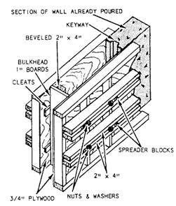
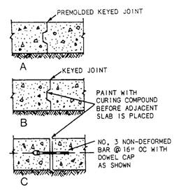
Figure 7-36.-Vertical bulkhead in wall using keyway. crack are usually sufficient to transfer loads across the joint in slabs on grade. Construction Joints Construction joints (figures 7-36,7-37,7-38, and 7-39) are made where the concrete placement
Figure 7-37.-Keyed wall construction joint.
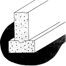
Figure 7-38.-Construction Joint between wail and footing with a keyway.
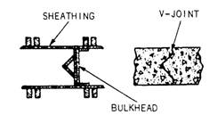
Figure 7-39.-Types of construction Joints. operations end for the day or where one structural element is cast against previously placed concrete. These joints allow some load to be transferred from one structural element to another through the use of keys or (for some slabs and pavement) dowels. Note that the construction joint extends entirely through the concrete element. SAWING CONCRETE LEARNING OBJECTIVE: Upon completing this section, you should be able to determine proper occasions for using the concrete saw. THE CONCRETE SAW The concrete saw is used to cut longitudinal and transverse joints in finished concrete pavements. The saw is small and can be operated by one person (figure 7-40). Once the cut has been started, the machine provides its own tractive power. A water spray is used to flush the saw cuttings from the cutting area and to cool the cutting blade. Several types of blades are available. The most common blades have either diamond or Carborundum cutting surfaces. The diamond blade is used for cutting hard or old concrete; the Carborundum blade is used for cutting green concrete (under 30 hours old). Let's take a closer look at these two blades. |
|
Privacy Statement - Press Release - Copyright Information. - Contact Us - Support Integrated Publishing |