Custom Search
|
|
  |
|
|
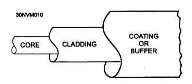
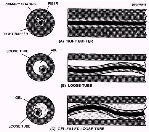
BASIC STRUCTURE OF AN OPTICAL FIBER The basic structure of an optical fiber consists of three parts: the core, the cladding, and the coating or buffer. The basic structure of an optical fiber is shown in figure 6-6. The core is a cylindrical rod of dielectric material. Dielectric material conducts no electricity. Light propagates mainly along the core of the fiber. The core is generally made of glass. The core is surrounded by a layer of material called the cladding. Even though light will propagate along the fiber core without the layer of cladding material, the cladding does perform some necessary functions. The cladding layer is made of a dielectric material. Cladding is generally made of glass or plastic and performs the following functions: Reduces loss of light from the core into the surrounding air Reduces scattering loss at the surface of the core Protects the fiber from absorbing surface contaminants Adds mechanical strength For extra protection, the cladding is enclosed in an additional layer called the coating or buffer. The coating or buffer is a layer of material used to protect an optical fiber from physical damage. The material used for a buffer is a type of plastic. The buffer is elastic in nature and prevents abrasions. Also, the buffer prevents the optical fiber from scattering losses caused by microbends. Microbends occur when an optical fiber is placed on a rough and distorted surface. Microbends are discussed later in this chapter. OPTICAL CABLES Optical fibers have small cross-sectional areas. Without protection, optical fibers are fragile and can be broken. The optical cable structure protects optical fibers from environmental damage. Cable structure includes buffers, strength members, and jackets. Many factors influence the design of fiber-optic cables. The cable design relates to the intended application of the cable. Properly designed optical cables perform the following functions: Protect optical fibers from damage and breakage during installation and over the lifetime of the fiber. Provide stable fiber transmission characteristics compared with uncabled fibers. Stable transmission includes stable operationin extreme climate conditions. Maintain the physical integrity of the optical fiber by reducing the mechanical stresses placed on the fiber during installation and use. Static fatigue caused by tension, torsion, compression, and bending can reduce the lifetime of an optical fiber. FIBER BUFFERS Coatings and buffers protect the optical fiber from breakage and loss caused by microbends. During the fiber drawing process, the addition of a primary coating protects the bare glass from abrasions and other surface contaminants. For additional protection, manufacturers add a layer of buffer material. The buffer material provides additional mechanical protection for the fiber and helps preserve the inherent strength of the fiber. Manufacturers use a variety of techniques to buffer optical fibers. The types of fiber buffers include tight-buffered, loose-tube, and gel-filled loose-Figure
6-6.- Basic structure of an optical fiber. tube. Figure 6-7 shows each type of fiber buffer. The choice of buffering techniques depends on the intended application. In large fiber count commercial applications, manufacturers use the loose-tube buffers. In commercial building and Navy applications, manufacturers use tight buffers. CABLE STRENGTH AND SUPPORT MEMBERS fibers, glass fibers, and glass reinforced plastics. Fiber-optic cables use strength members to increase the strength of the cable and protect the fiber from strain. Fiber-optic cables may use central support members in cable construction The central support members generally have buffered fibers or single fiber subcables stranded over their surface in a structured, helical manner. The central members may support the optical fibers as cable strength members or may only serve as fillers. Strength and support members must be light and flexible. The materials used for strength and support include steel wire and textile fibers (such as nylon and arimid yarn). They also include carbon CABLE JACKET MATERIAL The jacket, or sheath, material provides extra environmental and mechanical protection. Jacket materials may possess any number of the following properties: Low smoke generation Low toxicity Low halogen content Flame retardance Fluid resistance High abrasion resistance Stable performance over temperature It is difficult to produce a material compound that satisfies every requirement without being too costly. Jacket materials currently used include polyethylene, polyvinyl chloride, polyurethane, and polyester elastomers. Most commercial jacket materials are unsuitable for use in naval applications.
Figure 6-7.- Tight-buffered, loose-tube, and gel-filled loose-tube buffer techniques.
|
 
|
|
|