Custom Search
|
|
  |
|
|
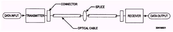
CABLE DESIGNS Manufacturers design fiber-optic cables for specific applications. For example, is the cable buried underground or hung from telephone poles? Is the cable snaked through cableways, submerged in water, or just laid on the ground? Is the cable used in industrial, telecommunication, utility, or military applications? Each type of application may require a slightly different cable design. Agreement on standard cable designs is difficult. Cable design choices include jacket materials, water-optic cables. Some fiber-optic cables are used in commercial applications, and others are used in military applications. Standard commercial cable designs will develop over time as fiber-optic technology becomes more established. FIBER-OPTIC DATA LINKS A fiber-optic data link sends input data through fiber-optic components and provides this data as output information. It has the following three basic functions: To convert an electrical input signal to an optical signal To send the optical signal over an optical fiber To convert the optical signal back to an electrical signal A fiber-optic data link consists of three parts: transmitter, optical fiber, and receiver. Figure 6-8 is an illustration of a fiber-optic data-link connection. The transmitter, optical fiber, and receiver perform the basic functions of the fiber-optic data link. Each part of the data link is responsible for the successful transfer of the data signal. A fiber-optic data link needs a transmitter that can effectively convert an electrical input signal to an optical signal and launch the data-containing light down the optical fiber. Also, fiber-optic data link needs a receiver that can effectively transform this optical signal back into its original form. This means that the electrical signal provided as data output should exactly match the electrical signal provided as data input. FIBER-OPTIC SPLICES A fiber-optic splice is a permanent fiber joint whose purpose is to establish an optical connection between two individual optical fibers. System design may require that fiber connections have specific optical properties (low loss) that are met only by fiber splicing. Also, fiber-optic splices permit the repair of optical fibers damaged during installation, accident, or stress. System designers generally require fiber splicing whenever repeated connection or disconnection is unnecessary or unwanted. Mechanical and fusion splicing are two broad categories that describe the techniques used for fiber splicing. A mechanical splice is a fiber splice where mechanical fixtures and materials perform fiber alignment and connection. A fusion splice is a fiber splice where localized heat fuses or melts the ends of two optical fibers together. Each splicing technique seeks to optimize splice performance and reduce splice loss. Low-loss fiber splicing results from proper fiber end preparation and alignment. FIBER-OPTIC CONNECTORS A fiber-optic connector is a device that permits the coupling of optical power between two optical fibers or two groups of fibers. Designing a device that allows for repeated fiber coupling without significant loss of light is difficult. Fiber-optic connectors must maintain fiber alignment and provide repeatable loss measurements during numerous connections. Fiber-optic connectors should be easy to assemble (in a laboratory or field environment) and should be cost effective. Also, they should be reliable. Fiber-optic connections using connectors should be insensitive to environmental conditions, such as temperature, dust, and moisture. Fiber-optic connector designs attempt to optimize connector performance by meeting each of these conditions.
Figure 6-8.- Parts of a fiber-optic data link.
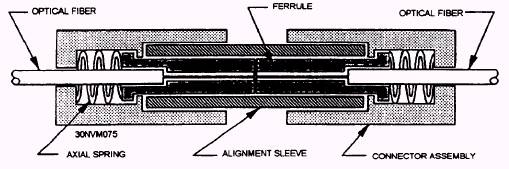
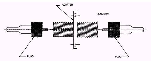
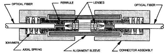
Figure 6-9.- Basic ferrule connector design. Butt-jointed connectors and expanded-beam connectors are the two basic types of fiber-optic connectors. Fiber-optic butt-jointed connectors align and bring the prepared ends of two fibers into close contact. The end faces of some butt-jointed connectors touch, but others do not. depending upon the connector design. Types of butt-jointed connectors include cylindrical ferrule and biconical connectors. Figure 6-9 shows a basic ferrule design. Fiber-optic expanded-beam connectors use two lenses to first expand and then refocus the light from the transmitting fiber into the receiving fiber. Single fiber butt-jointed and expanded-beam connectors normally consist of two plugs and an adapter (coupling device) (fig. 6-10). Expanded-beam connector shown in figure 6-11 uses two lenses to expand and then refocus the light from the transmitting fiber into the receiving fiber. Expanded-beam connectors are normally plug-adapter-plug type connections Fiber separation and lateral misalignment are less critical in expanded-beam coupling than in butt-jointing. The same amount of fiber separation and lateral misalignment in expanded-beam coupling produces a lower coupling loss than in butt-jointing; however, angular misalignment is more critical. The same amount of angular misalignment in expanded-beam coupling produces a higher loss than in butt-jointing. Also, expanded-beam connectors are much harder to produce. Resent applications for expanded-beam connectors include multifiber connections, edge connections for printed circuit boards, and other applications. FIBER-OPTIC COUPLERS Some fiber-optic data links require more than simple point-to-point connections. These data links may be of a much more complex design that requires multiport or other types of connections. In many cases, these types of systems require fiber-optic components that can redistribute (combine or split) optical signals throughout the system. One type of fiber-optic component that allows for the redistribution of optical signals is a fiber-optic coupler. A fiber-optic coupler is a device that can distribute the optical signal (power) from one fiber among two or more fibers. Also, a fiber-optic coupler
Figure 6-10.- Plug-adapter-plug configuration.
Figure 6-11.- Expanded-beam connector operation. can combine the optical signal from two or more fibers into a single fiber. Fiber-optic couplers can be either active or passive devices. The difference between active and passive couplers is that a passive coupler redistributes the optical signal without optical-to-electrical conversion. Active couplers are electronic devices that split or combine the signal electrically and use fiber-optic detectors and sources for input and output. Figure 6-12 shows the design of a basic fiber-optic coupler. A basic fiber-optic coupler has N input ports and M output ports. N and M ports typically range from 1 to 64. The number of input ports and output ports varies, depending on the intended application for the coupler. Types of fiber-optic couplers include optical splitters, optical combiners, X couplers, star couplers, and tree couplers.
|
 
|
|
|