Custom Search
|
|
 
|
||
|
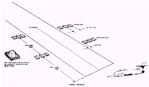
Approach Lights Runway approach light systems are used on high-intensity-equipped runways. The system starts at the threshold and extends outward for 3,000 feet. Where the full length of the land cannot be used, the greatest length possible is used. Condenser discharge (strobe) lights that put out a high-intensity, bluish white light start at the 3,000-foot mark and flash in sequence toward the threshold. The system is used to help the pilots land under low-visibility conditions. (This is discussed in more detail later in this chapter.) The lights of the approach system are located on an imaginary line that extends from the runway center line. Each light bar is centered on this imaginary line and spaced the same distance apart for the entire 3,000 feet. The supply and control circuits of the approach lighting systems are installed underground and are usually in conduit. However, in some cases, the last 2,000 feet of the approach lights can be above ground. In some cases, the supply cable from the series circuit can be direct burial. The direct burial method of cable installation will be discussed in another chapter. Aboveground circuits may be used for approach lighting when the cables do not present a hazard to vehicular traffic or are not accessible to unauthorized personnel and animals. The cable must be installed, normally, a minimum of 22 feet above ground. Where the area is completely closed off (fenced), a lower ground clearance is acceptable. Control circuits may use a small-size conductor when it is supported by a messenger cable. DO NOT USE ALUMINUM CONDUC-TORS. Use standard overhead construction practices for series circuits. Use lightning arresters when the cables go from underground to overhead. Connect the ends of the circuits to ITs the same way as underground cables. Besides the basic runway light configurations, there are other airfield lighting aids to help the pilot in landing and takeoff operations. Four such aids for landing and taking off are the visual approach slope indicators (VASI), the FLOLS, the runway distance markers, and the threshold lights. VISUAL APPROACH SLOPE INDICA-TORS (VASI).\The VASI system helps the pilot to make a visual glide slope landing approach. When there is an electronic glide slope system, the VASI system must be set up to give the same indication. The VASI system consists of twelve light boxes with three lights in each box. There is one complete system for each end of the runway. There are two pairs of bars, one bar on each side of the runway. Each wing bar is composed of
Figure 2-6.\Typical airfield lighting layout.
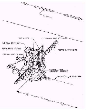
three light boxes. (See fig. 2-7.) The pair of bars nearest the threshold is called the downwind bars, and the other pair, the upwind bars. Each light box projects a beam of light that is white (clear) in its upper part and red in its lower part. The lights are so arranged that the pilot of an airplane, during the approach, sees all of the wing bar lights as red when below the glide slope. When on the glide slope, the pilot sees the downwind bar light as white, the upwind bar as red. When above the glide slope, the pilot sees all the wing bar lights as white. FRESNEL LENS OPTICAL LANDING SYSTEM (FLOLS).\Another system designed for continuous automatic operation is the FLOLS. (See fig. 2-8.) It also provides optical landing assistance by indicating the correct glide slope angle to the pilot of an approaching aircraft. This system contains two groups of horizontal datum lights set perpendicular to the approach path, two vertical bars of wave off lights, two double-type cut lights, and a source light indicator assembly, consisting of five vertical cell assemblies. Each cell assembly contains source lights, a Fresnel lens, and a lenticular lens. The arrangement of these lenses gives the pilot the glide slope. The unit should be set up on the left side of the runway with respect to the approaching plane, about 10 feet from the edge of the pavement and 750 feet from the runway threshold. Power for the system is provided by an installed field lighting supply or by an auxiliary power unit capable of 20 kW, 60 Hz, three-phase, 120 volts phase to neutral. RUNWAY DISTANCE MARKER.\With the use of high-speed aircraft, the runway distance marker system is needed to tell the pilots how much runway is left to take off or to land. The distance information, in thousands of feet, is given by numbers on the side of the marker. The numbers are on two sides of the signs, so that the distance left can be shown for both directions. There is one row of signs on each side of the runway. Each row is the same distance from the runway center line. They are spaced 1,000 feet apart. The signs have painted numbers that are lit so they can be seen at night and during periods of restricted visibility.
Figure 2-7.\Visual approach slope indicators (VASI).
Figure 2-8.\Fresnel lens optical landing system. The power supply should be from a separate series circuit for serving the runway distance markers. Do not have the markers supplied from circuits feeding either the runway, threshold, or the approach lighting circuits, since these circuits are operated at various brightness steps, and the signs are operated at their full brightness at all times. Also, do not connect them to taxiway circuits because of the intermittent operation requirements. The cable used for the circuit is a single conductor, No. 8 AWG, stranded, 5,000 volts. THRESHOLD LIGHTS.\The threshold lights are a part of the approach light system. Four sets of light systems are used in the threshold light configuration. These lights are as follows: inboard threshold lights, winged-out threshold lights, prethreshold wing bars, and a terminating bar. These four sets of lights are installed on both ends of the runway and are used to mark the beginning of the runway. Inboard Threshold Lights.\Inboard threshold lights are installed in the area at the end of the runway between the two runway edge light lines. This line of lights will be at a right angle to the runway center line. They are as close to the full-strength paving as possible but not more than 10 feet from it. The lights are spaced 10 feet apart. Their color is aviation green. (See fig. 2-6.) Winged-Out Threshold Lights.\The wingedout threshold light bar is on the same light line as the inboard lights. These lights extend out from the end of each side of the inboard light bar. Each bar is 40 feet long and has nine lights spaced 5 feet apart. The first light location is at the intersection of the runway edge light line and the threshold light line. The color of these lights is also aviation green. (See fig. 2-6.) Pre-threshold Wing Bars.\A pre-threshold wing bar is located on each side of the extended runway center line 100 feet out from the threshold. The innermost light of the bar is 75 feet from the center line. Each bar (14 feet long) has five aviation red lights spaced 3 1/2 feet apart. (See fig. 2-6.) Terminating Bar.\The terminating bar is located in the overrun area. The light bar is at a right angle to the runway center line and 200 feet out from the runway threshold (100 feet out from the pre-threshold lights). There are 11 aviation red lights in the bar. The bar is 50 feet long and is arranged so that one-half of the bar is on each side of the center line. The lights are arranged in three groups: five lights spaced 3 1/2 feet apart on a 14-foot bar in the middle and, on each side, one lo-foot bar of three lights spaced 5 feet apart. (See fig. 2-6.) |
 |
|
|
||