Custom Search
|
|
 
|
||
|
Obstruction Lights The obstruction lighting is a system of red lights used to show the height and width of natural or man-made objects that are hazardous to air flight. These lights are for the safety of aircraft in flight. The lights must be seen from all directions and are aviation red in color. The obstruction lights are turned on during all hours of darkness and during periods of restricted visibility. They are placed on all objects with an overall height of more than 150 feet above ground or water within the airspace. At least two lights (or one light fixture with two lamps) are located at the top of the obstruction. When the top of an obstruction is more than 150 feet above the level of the surrounding ground, an intermediate light, or lights, is provided for each 150 feet. These lights are equally spaced from the top to the bottom. Where obstructions cover an extensive horizontal plane, the top lights will be put on the point or edge of the obstruction highest in relation to the obstruction-marking surface. The lights should not be spaced more than 150 feet apart. This spacing indicates the general extent of the obstruction. Double lights are used at the horizontal limits of the obstruction, and single lights are used for intermediate lights. If two or more edges are of the same height, the edge nearest the airfield is lit. On overhead wires, obstruction lights are placed at intervals not exceeding 150 feet and at a level not below that of the highest wire at each light location. Obstruction lighting systems are served by either a series or a multiple circuit. The type of circuit used depends on the location of the obstruction and the type of lighting equipment installed. The six most common types of circuits that may be used for the obstruction lights are as follows: 1. Low-voltage multiple service from the vault when the length of the circuit is less than 800 feet 2. Series circuit when the load is less than 4 kW from a taxiway type of regulator in the vault 3. 2,400-volt service from the vault to a distribution transformer to serve a multiple circuit 4. 2,400-volt service from the vault to a CCR that serves a series circuit 5. Control circuit from the vault which operates any of the previously listed circuits by means of a relay 6. Time clock or a photocell with a series or multiple circuit for the lights Obstruction lights on objects that are more than 150 feet above ground or water must be on all the time or controlled by a photocell.
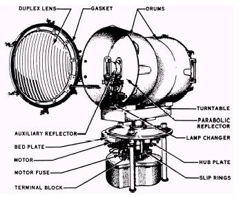
Beacon Lights The landing facility location is provided by the aeronautical beacon. The beacon is a high candlepower flashing light visible throughout 360. It provides the pilot a visual signal to locate and identify airfields during night operations or during periods of restricted visibility, day or night. There are three functional types of beacons that we will discuss: the airport beacon, the identification or code beacon, and the hazard or obstruction beacon. The airport beacon is normally located within 5,000 feet of the airfield. The rotatable unit will display alternate double-peaked white flashes and a single green flash to identify the airfield as a military facility. The size of the unit is about 24 inches, a rigid drum duplex type with a clear double-flasher spread-light lens on one end and a plain green lens on the other. There is an automatic built-in lamp change in case of lamp burnout. An illustration of a typical airport beacon is shown in figure 2-9. Beacon lights may be manually controlled from the tower or from the lighting vault. If the facility is not operated on a 24-hour basis, an automatic control is possible with a photoelectric control that turns the unit on or off automatically. The identification beacon or code beacon identifies an airfield where the airport beacon is more than 5,000 feet away from the airfield or where two or more airfields are close enough to use the same airport beacon. This nonrotatable unit can be seen from all directions and is equipped with a flasher switch operating at 40 flashes per minute with a range adjustment. The beacon has white lenses with green filters and is manually controlled from the tower but may be controlled automatically. The third beacon, the hazard or obstruction beacon, furnishes visual identification of natural features or structures which are 150 feet above airfield elevation for on-station or off-station hazards; that is, tanks, towers, stacks, and so forth. The beacon uses white lenses with red filters and is manually controlled from the tower. When automatic controls are desirable, a photoelectric control system may be used. Since the beacon does not rotate, a flashing system is used, flashing 26 times per minute. The beacon lamps and motor require 120 volts for operation. Most of the time, this unit is fed by a 120/240-volt or 120/208-volt, three-wire service. You can use a 120-volt, twowire service, but it is not recommended. When the lighting vault is less than 800 feet away from the beacon, a low-voltage service can be used. When the vault is more than 800 feet away, high voltage (2,400 volts) from the lighting vault is used to supply a distribution transformer at the base of the beacon. You can also run a control wire from the vault to the beacon to operate a relay that, in turn, switches on the power from a local source near the beacon. The last method works best when the beacon is at a remote location from the airfield.
Figure 2-9.\Beacon with one door open and base pan dropped.
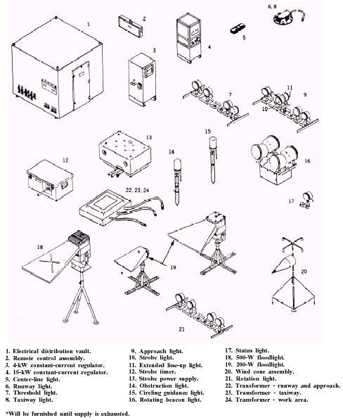
Figure 2-10.\Airfield lighting components.
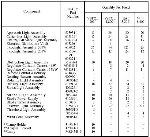
Table 2-1.\Airfield Lighting Equipment Required
*616040-1 and 614384 replaced with 618650 and 616360, respectively when supply is exhausted. **Components of extended line-up light. Because of the extreme hazard to life, an used to give off the right kind of light. A alternate low-voltage source near the beacon is runway light fixture, in a series loop system, usually required. requires an insolation transformer (IT). These transformers must be matched to each lamp TYPES OF FIXTURES AND LAMPS according to amperage and watts. Figure 2-10 provides you a pictorial view of the lighting To meet different system requirements, fixtures used in contingency airfield operadifferent intensities of lighting are required. Along tion; table 2-1 provides the Naval Air System with these systems, you need different kinds of Command part number of each fixture plus the fixtures to meet the needs of designated locations. number of fixtures required per given type of field In each fixture, a certain type of lamp must be installation.
Several different types of lights are used. The exact type used depends on the system. Not only are there different fixtures for different widths of runways, but there are different intensities. In most cases, high-intensity lighting systems are used for high-speed aircraft. Also, high-intensity lighting systems are required during low-visibility conditions. |
 
|
|
|
||
|
|
Integrated Publishing, Inc. - A (SDVOSB) Service Disabled Veteran Owned Small Business
|