Custom Search
|
|
 
|
||
|
CONDENSER DISCHARGE LIGHTING SYSTEM The condenser discharge lights are added to make the approach system complete. Because the lamps flash on and off to give a stroboscopic effect, the term strobe is used for these lights. From here on out, the term strobe will be used when referring to condenser discharge lights. The transformer and the master sequence timer cabinet are located in a small vault or pad near the center of the approach system. The vault or pad should be secured so neither animals nor unauthorized personnel can enter. The major components of the condenser discharge lighting system are the elevated and semiflush strobe light units, the master sequence timer cabinet (containing the local/remote control unit, the monitor and control chassis, and the master sequence timer), and the tower control unit.
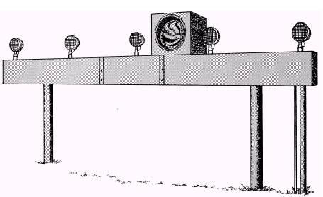
Strobe Light System The strobe lights are installed on each centerline light bar starting 300 feet from the runway threshold and extending outward for the length of the system. The strobe light will be located on the center-line light bar, midway between the center light and the next light on either the left or right side. They can be placed in front of the light bar but not more than 10 feet. No matter where they are placed, they must be in the same position on each light bar throughout the entire approach system. In the overrun area, the strobe lights are installed as flush lights. Starting with the 1,000-foot bar (decision bar) and going out, an elevated type of strobe light is used. An elevated approach light bar looks like the one shown in figure 2-11. The strobe lights are controlled from the remote control panel. They can be turned on and off independently or so triggered that they come on when the approach light switch is in either the third, fourth, or fifth brightness position.
Figure 2-11.\Elevated approach light bar. The brightness of the strobe lights cannot be controlled. knowledge of one will give you an understanding of the others. The strobe lights put out a high beam of light that peaks at 30 million candlepower. DO NOT LOOK INTO THE BEAM OF LIGHT WHEN YOU ARE NEAR ONE OF THE LAMPS OR YOUR EYES COULD BE DAMAGED. The system we discuss here is one of several different types manufactured. The operation is the same way no matter who manufactures them. Strobe lights are either flush mounted or elevated. Since the components are easier to see on an elevated unit, we will illustrate our discussion with an elevated unit, as shown in figure 2-12. The operation of the flush light is exactly the same as that of the elevated light unit. The main difference between the units is the way the components are arranged.
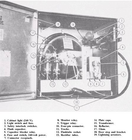
Figure 2-12.\Condenser discharge light.
Each strobe light has four inputs from the rest of the system: (1) 240 volts ac, (2) ground, (3) 120 volts ac timing pulses at the rate of two per second, and (4) a dc voltage connection to the monitor system. These inputs are plugged into a cable through a four-pin connector (No. 10). The unit steps up the 240 volt ac input voltage to 1,460 volts ac with a transformer (No. 15) and passes this voltage through a full-wave rectifier circuit of vacuum tubes (No. 13). The resultant 2,000 volts dc is applied to the electrodes of a flashtube and across the flash capacitor (No. 4). The xenon-filled flashtube will fire only when ionization is initiated by a trigger pulse of about 5,000 volts applied to its third electrode. This pulse is supplied by a trigger coil. At the same time that the flash capacitor is storing its charge, the trigger capacitor is also being charged by the primary of the trigger coil, which is an autotransformer and cuts the bleeder resistors in series out of the circuit. When the 120 volt ac timing signal arrives, it is applied to the coil of the trigger relay (No. 9), thus closing the relay contacts, allowing the trigger capacitor to discharge through the primary of the trigger coil. This generates the necessary trigger pulse in the secondary of the trigger coil, the flashtube fires, and the flash capacitor discharges across the flashtube electrodes. The flash capacitor discharges down to the deionization potential of the flashtube, at which point the tube becomes a nonconductor. The light-producing arc ceases, and the charge cycle begins again. The charge stored in the flash capacitor is a potential safety hazard. To make sure that the capacitor is discharged when the light unit is shut off, provide a discharge circuit by a series of bleeder relays. The bleeder relay (No. 5) closes this discharge circuit when the power to the transformer is turned off. The current that charges the flash capacitor creates a pulse voltage in a surge resistor twice each second. A part of this voltage is applied to a silicon rectifier through a tap-off of the surge resistor. The rectified voltage is then filtered and applied to the monitor relay. The value of this voltage is sufficient to keep the monitor relay energized when the unit is flashing normally. When the unit stops operating because of a component failure in the unit, the absence of the pulse voltage at the surge resistor will allow the contacts of the monitor relay to close. This action completes a circuit from the monitor connection through a monitor resistor of 22 kilohms to ground. The monitor and control chassis react to the ground by warning the operator.
|
 
|
|
|
||
|
|
Integrated Publishing, Inc. - A (SDVOSB) Service Disabled Veteran Owned Small Business
|