Custom Search
|
|
 
|
||
|
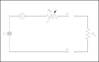
The resistance of a wire or a circuit is measured by an ohm meter. An ohm meter aids the troubleshooter in determining if a ground or a short exists in a circuit. EO 1.2STATE the electrical parameters measured by each of the following in-place measuring devices: c. Ohm meter EO 1.3EXPLAIN how the following electrical test equipment and measuring devices are connected to a circuit: c. Ohm meter Ohm Meter The ohm meter is an instrument used to determine resistance. A simple ohm meter (Figure 9) consists of a battery, a meter movement calibrated in ohms, and a variable resistor.
Figure 9 Simple Ohm Meter Circuit Ohm meters are connected to a component which is removed from the circuit as illustrated in Figure 9. The reason for removing the component is that measurement of current through the component determines the resistance. If the component remains in the circuit, and a parallel path exists in the circuit, the current will flow in the path of least resistance and give an erroneous reading. Ro, in Figure 9, is an adjustable resistor whose purpose is to zero the ohm meter and correct for battery aging. It is also a current-limiting resistor which includes the meter resistance Rm. Zeroing the ohm meter is accomplished by shorting the ohm meter terminals ab and adjusting Ro to give full-scale deflection. Equation (14-10) is the mathematical representation for determining full-scale deflection meter current.
When the unknown resistance Rx is connected across the ohm meter terminals, the current is measured by calculating the total series resistance and applying Equation (14-10). Equation (14-11) is the mathematical representation of this concept.
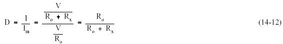
An easy way to determine ohm meter deflection is by use of a deflection factor (D). Deflection factor is the ratio of circuit current to meter current. Equation (14-12) is the mathematical representation of the deflection factor.
The current through the circuit can be determined by solving for I. Equation (14-13) is the mathematical representation of this relationship.
To solve for Rx using Equations (14-10) through (14-13), the relationship between deflection factor and the meter resistance to the unknown resistance can be shown. Equation (14-14) is the mathematical representation of this relationship.
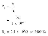
If half-scale deflection occurs, then Rx = R0, so that the value of R0 is marked at mid-scale on the ohm meter face. Example
1: An ohm meter has a meter movement
with a 100 Solution: First find Ro.
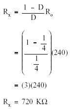
Then solve for Rx:
Therefore,
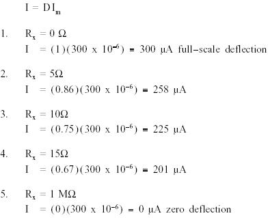
quarter scale deflection of this ohm meter face would read 720 K Example
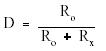
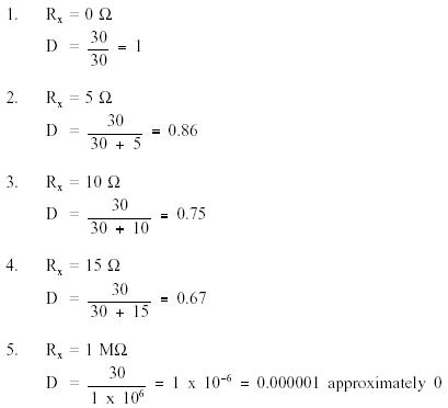
2: An ohm meter with R0 =
30 Solution: First, the deflection factor for each resistor must be found. R
Then find I by using:
NOTE:As the resistance was increased from 0 to 552,
meter current decreased by 42
Figure 10 Ohm Meter Scale Summary Ohm meters are summarized below. Ohm Meter Summary Measures circuit resistance Connected to a component removed from the circuit
|
 |
|
|
||