Custom Search
|
|
 
|
||
|
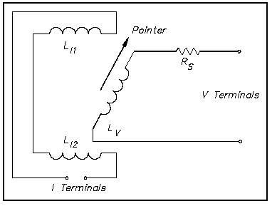
Wattmeters are used to determine DC power or real AC power delivered to the load. EO 1.2 STATE the electrical parameters measured by each of the following in-place measuring devices: d. Wattmeter EO 1.3 EXPLAIN how the following electrical test equipment and measuring devices are connected to a circuit: d. Wattmeter Wattmeter The wattmeter is an instrument which measures DC power or true AC power. The wattmeter uses fixed coils to indicate current, while the movable coil indicates voltage (Figure 11). Coils 1-11 and LIZ are the fixed coils in series with one another and serve as an ammeter. The two I terminals are connected in series with the load. The movable coil L, and its multiplier resistor RS, are used as a voltmeter, with the V terminals connected in parallel with the load. The meter deflection is proportional to the VI, which is power.
Figure 11 Wattmeter Schematic Wattmeters are rated in terms of their maximum current, voltage, and power. damage to the meter. All of these ratings must be observed to prevent Equation (14-15) is the mathematical representation of calculating power in a DC circuit.
Equation (14-16) is the mathematical representation for calculating power in an AC circuit.
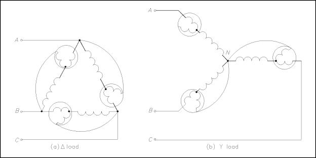
Three-Phase Wattmeter Total power in a 30 circuit is the sum of the powers of the separate phases. The total power could be measured by placing a wattmeter in each phase (Figure 12); however, this method is not feasible since it is often impossible to break into the phases of a delta load. It also may not be feasible for the Y load, since the neutral point to which the wattmeters must be connected is not always accessible.
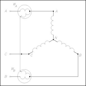
Figure 12 Wattmeters in Each Phase Normally, only two wattmeters are used in making 30 power measurements (Figure 13). In balanced 30 systems, with any power factor, total power is calculated by adding the A and B phase powers. Equation (14-17) is the mathematical representation for calculating total power (PT).
where WA and WB are the power readings in Phase A and Phase B
Figure 13 Two Wattmeters to Measure 30 Power Summary Wattmeters are summarized below. Wattmeter Summary Measures real power delivered to the load Single-phase AC or DC - voltage component (movable coil) connected in parallel with the load and the current component (fixed coil) connected in series with the load Three-phase AC - summation of Phase A and B powers
|
||
|
||