Custom Search
|
|
 
|
||
|
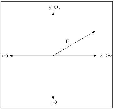
Before attempting to use this method, the following equipment is needed: standard linear (nonlog) graph paper, ruler, protractor, and pencil. The graphic method utilizes a five-step process. Step 1.Plot the first vector on the rectangular (x-y) axes. a. Ensure that the same scale is used on both axes. b. Place the tail (beginning) of the first vector at the origin of the axes as shown in Figure 16.
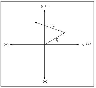
Figure 16 Rectangular Coordinate System Step 2. Draw the second vector connected to the end of the first vector. a. Start the tail of the second vector at the head of the first vector. b. Ensure that the second vector is also drawn to scale. c. Ensure proper angular orientation of the second vector with respect to the axes of the graph (see Figure 17).
Figure 17 - Vector F2 Step 3. Add other vectors sequentially. a. Add one vector at a time. b. Always start the tail of the new vector at the head of the previous vector. c. Draw all vectors to scale and with proper angular orientation.
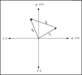
Figure 18 Resultant Step 4. When all given vectors have been drawn, draw and label a resultant vector, FR, from the point of origin of the axes to the head of the final vector. a. The tail of the resultant is the tail of the first vector drawn as shown in Figure 18. b. The head of the resultant is at the head of the last vector drawn.
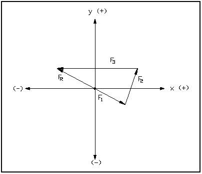
Step 5.Determine the magnitude and direction of the resultant. a. Measure the displacement and angle directly from the graph using a ruler and a protractor. b. Determine the components of the resultant by projection onto the x- and y-axes. Example 1: What are the magnitude and direction of the resultant for the following: Fl = 3 units at 300, F2 = 4 units at 60, and F3 = 8 units at 180? The three vectors and their resultant are shown in Figure 19. Answer: FR = 4 units at 150
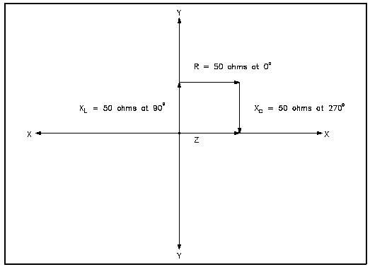
Figure 19 Graphic Addition - Example 1 Example 2: Given XL = 50 Ohms at 90, R = 50 Ohms at 0, and k = 50 Ohms at 270, what is the Resultant Z? (See Figure 20) Note: XL is inductive reactance, Xc is capacitive reactance and Z is impedance. Answer: Z = 50 Ohms at 0
Figure 20 Graphic Addition - Example 2 |
 
|
|
|
||
|
|
Integrated Publishing, Inc. - A (SDVOSB) Service Disabled Veteran Owned Small Business
|