| Tweet |

Custom Search
|
|
 
|
||
|
FUEL
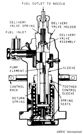
INJECTION EQUIPMENT There are three methods commonly used for the mechanical injection of fuel (at the proper amount, time, and duration) into the cylinders of a diesel engine. These methods are as follows: 1. Pump controlled (jerk pump) 2. Distributor 3. Unit injector NOTE: A fourth method, known as pressure-time (PT) uses unit injectors. This method is unique to Cummins diesel engines and is not considered to be common; therefore, it will not be explained in this rate training manual. The three methods listed above will be explained in the sections that follow. JERK PUMP FUEL INJECTION SYSTEM Jerk pump fuel injection systems consist of high-pressure pumps and pressure-operated spray valves or nozzles that are separate components. In some engines, such as the Alco, there is only one pump and one nozzle for each cylinder. In other engines, such as the Fairbanks-Morse opposed piston engine, each cylinder has two pumps and two nozzles. Most of the injection event is carried out by the pump itself. The pump raises pressure, meters the fuel, and times the injection. The nozzle is simply a spring-loaded check valve that reacts to the pressure supplied from the high-pressure pump. NOTE: A major manufacturer of jerk pump fuel injection systems is the American Bosch company. The system may use either of two different types of pumps, designated APF or APE. The letter F in APF identifies a pump that does not have its own drive, and the letter E in APE indicates a pump with a self-contained drive. Bosch APF Pump Type APF pumps are of the single-cylinder design with the plunger pump for each cylinder contained in separate housing (fig. 9-10). In a 6-cylinder engine, for example, there are six AMBAC International
Figure 9-10.-Type APF single cylinder, fuel injection pump. separate APF pumps. Each pump is cam driven and fuel volume is regulated by the setting of the control rack. Bosch APE Pump Figure 9-11 illustrates a typical Bosch APE fuel injection pump. Type APE pumps are assembled with all the individual cylinder plungers in a single housing. View A of figure 9-11 shows a typical fuel supply system. View B of figure 9-11 shows the pump assembly for a 6-cylinder engine. The injection pumps are operated from a single camshaft in the bottom part of the housing. The cam lobes are arranged so that the firing order is consistent with the engine firing order. Each revolution of the camshaft provides one fuel charge from each outlet. Although our discussion will be on the APE pump system, the APF pump operates on the same principles. Therefore, the information on
Figure 9-11.-Typical Bosch APE fuel supply system and fuel injection pump. the pumping principle, metering principle, and delivery valve operation also applies to the APF pump. |
||
|
||