| Tweet |

Custom Search
|
|
 
|
||
|
GENERAL
OPERATING PRINCIPLES.- As we discuss the operating principles of the APE
pump system, refer to views A and B of figure 9-11. (Unless otherwise
indicated, the letters used in parentheses in our explanation refer to the
letters used in view A of fig. 9-11.) Refer to view A as you follow our
explanation.
The supply pump (C) is a plunger-type, cam-activated pump that is equipped with inlet and outlet check valves and a hand-priming pump (D). The supply pump draws fuel from the fuel tank (A) through a primary filter (B) and discharges the fuel to a final stage filter (E). An arrow is stamped on the supply pump housing to indicate the direction of fuel flow. From the final stage filter, the fuel then flows into the injection pump sump (fuel gallery) which provides all six plunger and barrel assemblies with fuel. An overflow valve
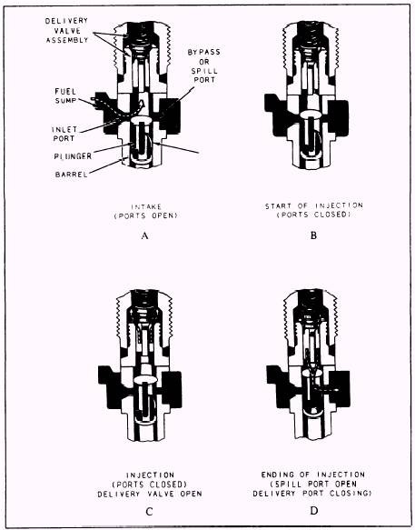
Figure 9-12.-Pumping principles of an APE pump. assembly (H), which regulates and maintains the pump sump (gallery) pressure, is attached to the injection pump housing (G). The overflow valve assembly also permits any air in the system to work its way out and return to the fuel tank. When the pump plunger is in its lowest position, fuel from the sump (gallery) enters the barrel ports and fills the volume above the plunger. The upward movement of the plunger (through cam action) seals off the barrel ports and forces fuel (now under high pressure) through the delivery valve assembly and high pressure tubing (J) to the holder and nozzle assembly (K). Fuel entering the nozzle holder inlet flows through passages to the nozzle, which contains a spring-loaded valve. Fuel pressure exerts a force against the lower end of the valve, which is opposed by the spring force. At a preset pressure, the spring force is overcome and the valve rises, thus permitting the fuel to flow through the nozzle spray holes (orifices) and into the combus-tion chamber. The slight fuel leakage between the nozzle valve and body (required for nozzle lubrication) is returned to the fuel tank through a leak-off line. Normally, the nozzle leak-off line is connected to the pump return line; thus both are returned to the fuel tank in a single line. So far, our discussion has been general. We will now discuss in more detail the principles by which the fuel is pumped, metered, and delivered to the nozzle. |
||
|
||