| Tweet |

Custom Search
|
|
 
|
||
|
PUMPING
PRINCIPLE.-We will first discuss the pumping principle behind the action of
the APE fuel pump as it operates to pump fuel. Refer to view A of figure 9-12.
When the plunger is at the bottom of its stroke, fuel from the pump sump flows
through the barrel ports and fills the volume above the plunger. The sump fuel
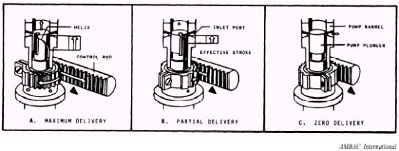
initially fills the vertical slots and connecting cutaway areas of the plunger. Upward movement of the plunger seals off the barrel ports, thus trapping fuel in the barrel (fig. 9-12, view B). Additional upward movement of the plunger (fig. 9-12, view C) forces fuel through the delivery valve, high-pressure tubing, nozzle, and finally to the combustion chamber. Fuel delivery will stop when the plunger helix uncovers the barrel port (fig. 9-12, view D). This action releases the trapped fuel through the slot in the plunger and out through the barrel ports. METERING PRINCIPLE.-Refer to figure 9-13 as you read how the fuel is metered and controlled. The positioning of the plunger helix is automatically controlled by movement of the speed governor output shaft, which is attached to the rear of the pump housing. The governor, through linkages, positions the control racks that rotate the segment gears and control sleeves which, in turn, radially position the plunger flange and helix. The fuel control rod (rack) teeth engage the plunger gear teeth to control fuel metering. Lateral movement of the fuel rack causes the plungers to rotate. This action, in turn, determines
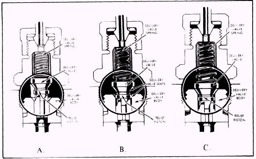
Figure 9-13.-Effects of plunger rotation on fuel delivery (metering principle). the effective stroke of the plunger by plunger helix position in relation to the barrel port. The amount of fuel delivered is controlled by the position of the plunger helix. When the plunger is rotated to a position as illustrated in view A, the effective part of the stroke (that position of the stroke from the closing of the barrel ports by the top of the plunger to the point where the edge of the helix raises above the barrel ports) is long, and fuel delivery is at a maximum. When the plunger is rotated to a position as shown in view B, the effective part of the stroke is reduced since the helix will uncover the barrel ports sooner (at a lower position). This action reduces the volume of fuel delivered to the cylinder. When the vertical slot on the plunger is in line with one of the barrel ports, as illustrated in view C, there is no effective stroke and therefore no fuel delivery. DELIVERY VALVE OPERATION.-As we discuss the delivery valve operation of the APE pump, you should refer to figure 9-14. The delivery valve assembly that was illustrated in figure 9-12 is shown close up in figure 9-14. The delivery valve assembly is located directly above the plunger. The delivery valve assembly assists the injection function by preventing irregular losses of fuel from the delivery to the supply side of the system between pumping strokes. The delivery valve assembly consists of a valve with a conical seat and a valve body with a corresponding mating seat. Opening pressure is controlled by the force of the delivery valve spring that engages the top of the valve. Since liquid fuel trapped in the barrel is essentially incompressible, pressure is created after the plunger, on its upward stroke, closes off the barrel ports. When this hydraulic pressure overcomes the force of the delivery valve spring, the valve opens and fuel passes through it into the injection tubing. When the edge of the plunger helix passes the lower edge of the barrel port, there is a rapid drop in fuel pressure below the delivery valve (view A), and the force of the valve spring, combined with the high differential in pressure, begins to return the valve to its seat. As the valve starts downward into the valve body (view B), the lower edge of its retraction piston enters the valve bore. At that moment, the flow of fuel by the delivery valve stops. In view C, the continued downward movement of the valve (retraction piston) increases the volume on
Figure 9-14.-Delivery valve in three positions. the high-pressure side by the amount of the piston retraction (its displacement volume) and, consequently, reduces the residual pressure in the injection tubing and nozzle holder. This lower pressure promotes rapid closing of the injection nozzle valve and diminishes the effect of hydraulic pressure waves that exist in the tubing between injections, thereby minimizing the possibility of the nozzle reopening (a secondary injection) before the next regular delivery cycle. |
||
|
||