| Tweet |

Custom Search
|
|
 
|
||
|
AIR
STARTING MOTOR SYSTEM
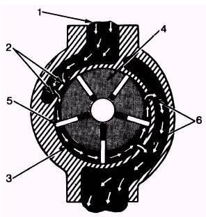
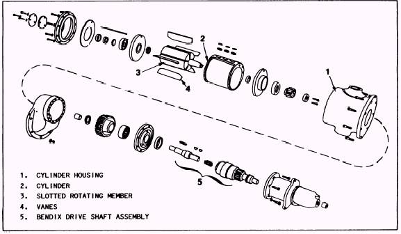
Some larger engines and several small engines are cranked over by starting motors that use compressed air. Air starting motors are usually driven by air pressures varying from 90 to 200 psi. Figure 10-8 shows an exploded view of an air starting motor with the major com-ponents identified. Figure 10-9 shows the principles by which the air starting motor functions. As you read the following dis-cussion on the flow of air through the starting motor, refer to figure 10-9. For the relative position of the principal components, refer to figure 10-8. In figure 10-9, starting air enters through piping into the top of the air starter housing (1) and flows into the top of the cylinder (2). The bore (3) of the cylinder has a larger diameter than the rotor. The rotor (4) in-side the cylinder is a slotted rotating member which is offset with the bore of the cylinder. The rotor carries the vanes (5) in slots, allowing the vanes to maintain contact with the bore of the cylinder. The pressure of the starting air against the vanes forces the rotating member to turn approximately half-way around the core of the cylinder, where exhaust ports (6) allow the air to escape to the atmosphere. A shaft and a reduction gear connect the rotating member to a Bendix drive, which engages the ring gear of the flywheel to crank the engine.
Figure 10-9.-Flow of air through an air starting motor.
Figure 10-8.-Air starting motor (exploded view). |
||
|
||