| Tweet |

Custom Search
|
|
 
|
||
|
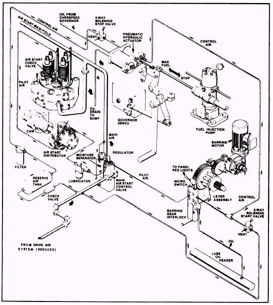
COMPRESSED AIR ADMISSION SYSTEM Most large diesel engines are started when compressed air is admitted directly into the engine cylinders. Compressed air at approximately 200 to 300 psi is directed into the cylinders to force the pistons down and thereby turn the crankshaft of the engine. This air admission process continues until the pistons are able to build up sufficient heat from compression to cause combustion to start the engine. Refer to figure 10-10. The engine is started by the admitting of compressed air into the right-hand bank of cylinders. Control valves and devices that permit compressed air to flow to the cylinders are actuated by control air that is directed through the engine control system. The heart of the engine control system is the main air start control valve. (A cutaway view of
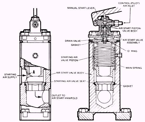
Figure 10-10.-Compressed air admission starting system (Colt-Pielstick). this valve is shown in fig. 10-11.) Except when the engine is being cranked, this component acts as a simple stop valve. A small amount of air is routed through the air supply port (A) to the spring side of the starting air valve. This air pressure, along with the force of the main spring, holds the main starting air valve against its seat. (Air pressure is the same on both sides of the piston inside the valve body; however, the surface area inside the piston (at the bottom) is less than the bottom area outside the piston. So the spring is required to hold the piston down against the seat. When air pressure acting on the piston becomes unbalanced, such as when air pressure on the inside of the piston is reduced, air pressure acting on the larger surface area on the outside of the piston will force the piston up off the seat of the starting air valve.) As long as the main starting air valve remains seated, starting air cannot pass through the control valve and enter the air start manifold. However, when compressed air is needed for the engine to start, the drain valve is forced downward, either by air that is brought in through the control air inlet by pilot air or by the pin attached to the manual start lever. When the drain valve is in the proper position, pressurized air above the main spring in the start control valve escapes through the vent ports at the top of the valve body. The resulting release of pressure allows the main starting valve to overcome the spring force and to lift off its seat. In turn, compressed starting air is permitted to pass through the control valve and into the air start manifold. Starting air will continue to pass through the main air start control valve until the drain valve is closed. When the drain valve closes, the area above the piston repressurizes and forces the main starting valve back on its seat. This
Figure 10-11.-Main air start control valve. reseating action shuts off starting air through the control valve. The air start manifold runs parallel to the right bank of cylinders. Jumper lines are connected only to the right bank of cylinders because only one bank of cylinders needs to be attached to the air starting system. The jumper lines connect the air start manifold to the air start check valves in the cylinder head and supply the required air pressure to the cylinders (fig. 10-10). The entry of starting air into the cylinders is controlled by pilot air. Pilot air leaves the main air start control valve, passes through an air filter and an oiler, and enters the air start distributor. The air distributor is directly driven by the right camshaft. As the camshaft rotates, pilot air is allowed to pass through a line to the appropriate air start check valve in the firing sequence. Pilot air opens each check valve to allow high-pressure starting air to enter the cylinder from the jumper line, force the piston downward, and rotate the crankshaft. The air start check valve functions as a pilot-actuated air admission valve until the cylinders begin to fire. As the cylinders fire, pressure created by combustion exceeds the pressure of the starting air, this condition forces the air start check valves to close, preventing combustion gases from entering the air start manifold. At the same time that starting air is delivered to the cylinders, control air at 200 psi is supplied to the forward end of the pneumatic auxiliary start/stop relay and the fuel rack activator piston. The control air causes the piston to pull the fuel racks toward the full-fuel position. Once the engine is started, its speed is controlled by a hydraulic governor with a pneumatic speed mechanism attached for remote engine control. The governor is also equipped with a dial that can be used for local control of engine speed during maintenance, or in an emergency. The control air that operates the main air start control valve passes through a primary safety device, the barring gear interlock (fig. 10-10). The barring gear interlock prevents the engine from accidentally starting or rotating and also prevents the barring gear from being engaged when the engine is running. The safety feature is provided by the barring lever assembly. When the barring lever assembly is in place, the interlock will not allow control air to reach the main air start control valve, and compressed air will not be admitted to the cylinders. Basically, all air starting systems operate similarly and contain components that are similar in function to those used in the two types of air starting systems we have discussed. |
||
|
||