| Tweet |

Custom Search
|
|
 
|
||
|
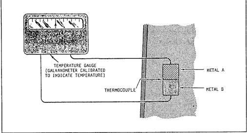
ELECTRICAL TEMPERATURE MEASURING DEVICES On newer propulsion plants, you will monitor temperature readings at remote locations. Expansion thermometers provide indications at the machinery locations or on gauge panels in the immediate thermometer area. To provide remote indications at a central location, electrical measuring devices along with signal conditioners are used. The devices discussed in this section include the resistance temperature detectors (RTDs), resistance temperature elements (RTES), and
Figure 11-14.-Diagram arrangement of a thermocouple.
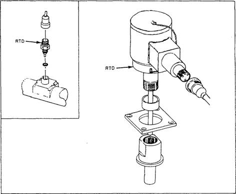
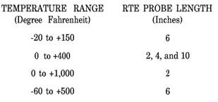
Figure 11-15.-Two typical types of RTDs. thermocouples. These devices sense variable temperatures at a given point in the system and transmit the signals to a remotely located indicater. Resistance Temperature Detectors The RTDs operate on the principle that electrical resistance changes in a predictable manner with changes in temperature. The elements of RTDs are made of nickel, copper, or platinum. Nickel and copper are used to measure temperatures below 600F. Platinum elements are used to measure temperatures above 600F. Figure 11-15 shows two typical types of RTDs. Like bimetallic thermometers, RTDs are usually mounted in thermowells. Thermowells protect the sensors from physical damage by keeping them isolated from the medium being measured. This arrangement also lets you change the RTD without securing the system in which it is mounted. This makes your maintenance job easier. As temperature increases around an RTD, the corresponding resistance also increases proportionally. The temperature applied to an RTD, if known, gives you a known resistance value. You can find these resistance values listed in tables in the manufacturers' technical manuals. Normally, only a few resistance values are given. To test an RTD, you need to heat it to a specific temperature. At this temperature, the resistance of the RTD should be at the resistance shown in the manufacturer's table. The most common method of heating an RTD is to use a pan of hot water and a calibrated thermometer. Some newer ships and repair activities test RTDs using. a thermobulb tester. This method is more accurate and easier to use. For specific instructions, refer to the manufacturers' technical manuals supplied with the equipment. The most common fault you will find with an RTD is either a short circuit or an open circuit. You can quickly diagnose these faults by using digital display readings or data log printouts. By observing the reading or the printout, you may find that the indication is either zero or a very low value. A malfunction of this type means a short circuit exists in either the RTD or its associated wiring. A very high reading, such as 300F on a 0F to 300F RTD, could indicate an open circuit. You should compare these readings to local thermometers. This precaution allows you to ensure that no abnormal conditions exist within the equipment that the RTD serves. If an RTD is faulty, you should replace it. Internal repairs cannot be made at the shipboard level. Until you can replace the faulty RTD, inform the watch standers that the RTD is unreliable. THe engine-room watch standers should take local readings periodically to make sure the equipment is operating normally. Resistance Temperature Elements The RTEs are the most common type of temperature sensor found in gas turbine propulsion plants. The RTEs operate on the same principle as the RTDs. As the temperature of the sensor increases, the resistance of the RTE increases proportionally. All RTEs that you encounter have a platinum element. They have an electrical resistance of 100 ohms at a temperature of 32F. Four different temperature ranges of RTEs are commonly used, and you will find that the probe sizes vary. The four temperature ranges and their corresponding probe sizes are as follows:
You may find some RTEs connected to remote mounted signal conditioning modules. These modules convert the ohmic value of the RTE to an output range of 4 to 20 mA dc. However, most RTES read their value directly into the propulsion electronics as an ohmic value. The RTEs with temperature ranges from 0F to +400F and from -60 to +500F are commonly mounted in thermowells. Since you can change an RTE without securing the equipment it serves, maintenance is simplified. |
 
|
|
|
||