| Tweet |

Custom Search
|
|
 
|
||
|
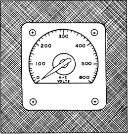
ELECTRICAL INDICATING INSTRUMENTS Electrical indicating instruments (meters) are used to display information that is measured by some type of electrical sensor. Although meters display units such as pressure or temperature, the meters on the control console are, in fact, do voltmeters. The signal being sensed is conditioned by a signal conditioner. This is
Figure 11-16.-An ac voltmeter. then converted to 0 to 10 volts dc, which is proportional to the parameters being sensed. Electrical values, such as power and current, are measured and displayed at ship's service switchboards. Normally, shipboard repair is not done on switchboard meters. If you suspect the switchboard meters are out of calibration or broken, you should have them sent to a repair facility. You can find more information on the theory of operation of these meters in the Navy Electricity and Electronics Training Series (NEETS), Module 3, Introduction to Circuit Protection, Control, and Measurement, NAVEDTRA 172-03-00-79. VOLTMETERS Both do and ac voltmeters determine voltage the same way. They both measure the current that the voltage is able to force through a high resistance. This resistance is connected in series with the indicating mechanism or element. Voltmeters installed in switchboards and control consoles (fig 11-16) all have a fixed resistance value. Portable voltmeters, used as test equipment, usually have a variable resistance. For both installed and portable voltmeters, resistances are calibrated to the different ranges that the meters will display. The normal range for the switchboard and electric plant meters is 0 to 600 volts.
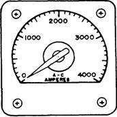
Figure 11-17.-An ac ammeter. AMMETERS Ammeters are used to measure the amount of current passing through a conductor (fig 11-17). Different types of ammeters are used to measure either ac or dc. Ammeters that are designed specifically to indicate ac will also measure dc, but with a lower degree of accuracy. Ammeters must be connected in series with the circuit to be measured. For this reason, installed ammeters are constructed so that they do not handle the current that passes through the conductor being measured. Since ammeters cannot handle the high switchboard current, the switchboard ammeters operate through current transformers. This arrangement isolates the instruments from the line potential. In its secondary, the current transformer produces a definite fraction of the primary current. This arrangement makes it possible for you to measure large amounts of current with a small ammeter. CAUTION The secondary of a current transformer contains a dangerous voltage. Never work around or on current transformers without taking proper safety precautions. |
 
|
|
|
||