| Tweet |

Custom Search
|
|
 
|
||
|
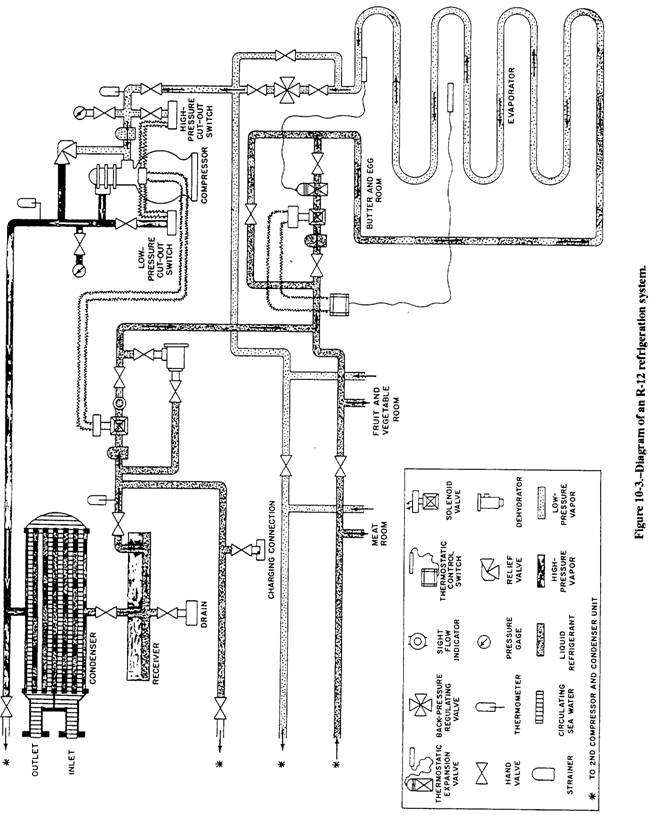
MAIN PARTS OF THE R-12 SYSTEM The main parts of an R- 12 refrigeration system are shown diagrammatically in figure 10-3 The six primary components of the system include the 1. TXV, 2. evaporator, 3. capacity control system, 4. compressor, 5. condenser, and 6. receiver.
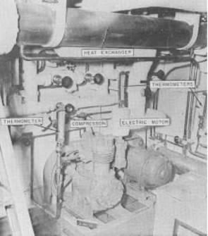
Figure 10-2.-High-pressure side of an R-12 installation aboard ship. Additional equipment required to complete the plant includes piping, pressure gauges, thermometers, various types of control switches and control valves, strainer, relief valves, sight-flow indicators, dehydrators, and charging connections. In this chapter, we will deal with the R-12 system as though it had only one evaporator, one compressor, and one condenser. As you can see from figure 10-3 however, a refrigeration system usually has more than one evaporator, and it may include an additional compressor and condenser units. Thermostatic Expansion Valve (TXV) Earlier, you learned that the TXV regulates the amount of refrigerant to the cooling coil. The amount of refrigerant needed in the coil depends, of course, on the temperature of the space being cooled. The thermal control bulb, which controls the opening and closing of the TXV, is clamped to the cooling coil near the outlet. The substance in the thermal bulb varies, depending on the refrigerant used. The expansion and contraction (because of temperature change) transmit a pressure to the diaphragm. This causes the diaphragm to be moved downward, opening
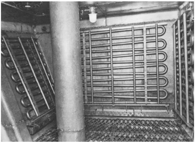
the valve and allowing more refrigerant to enter the cooling coil. When the temperature at the control bulb falls, the pressure above the diaphragm decreases and the valve tends to close. Thus, the temperature near the evaporator outlet controls the operation of the TXV. Evaporator The evaporator consists of a coil of copper, aluminum, or aluminum alloy tubing installed in the space to be refrigerated Figure 10-4 shows some of this tubing. As mentioned before, the liquid R-12 enters the tubing at a reduced pressure and, therefore, with a lower boiling point. As the refrigerant passes through the evaporator, the heat flowing to the coil from the surrounding air causes the rest of the liquid refrigerant to boil and vaporize. After the refrigerant has absorbed its latent heat of vaporization (that is, after it is entirely vaporized), the refrigerant continues to absorb heat until it becomes superheated by approximately 10F. The amount of superheat is determined by the amount of liquid refrigerant admitted to the evaporator. This, in turn, is controlled by the spring adjustment of the TXV. A temperature range of 4 to 12F of superheat is considered desirable. It increases the efficiency of the plant and evaporates all of the liquid. This prevents liquid carry-over into the compressor. Compressor The compressor in a refrigeration system is essentially a pump. It is used to pump heat uphill from the cold side to the hot side of the system. The heat absorbed by the refrigerant in the evaporator must be removed before the refrigerant can again absorb latent heat. The only way the vaporized refrigerant can be made to give up the latent heat of vaporization that it absorbed in the evaporator is by cooling and condensing it. Because of the relatively high
Figure 10-4.-Evaporator tubing. temperature of the available cooling medium, the only way to make the vapor condense is to compress it. When we raise the pressure, we also raise the temperature. Therefore, we have raised its condensing temperature, which allows us to use seawater as a cooling medium in the condenser. In addition to this primary function, the compressor also keeps the refrigerant circulating and maintains the required pressure difference between the high-pressure and low-pressure sides of the system. Many different types of compressors are used in refrigeration systems. The designs of compressors vary depending on the application of the refrigerants used in the system. Figure 10-5 shows a motor-driven, single-acting, two-cylinder, reciprocating compressor, such as those commonly used in naval refrigeration plants. Compressors used in R-12 systems may be lubricated either by splash lubrication or by pressure lubrication. Splash lubrication, which depends on maintaining a fairly high oil level in the compressor crankcase, is usually satisfactory for smaller compressors. High-speed or large-capacity compressors use pressure lubrications systems. |
||
|
||