| Tweet |

Custom Search
|
|
 
|
||
|
Capacity Control System Most compressors are equipped with an oil-pressure-operated automatic capacity control system. This system unloads or cuts cylinders out of operation following decreases in the refrigerant load requirements of the plant. A cylinder is unloaded by a mechanism that holds the suction valve open so that no gas can be compressed. Since oil pressure is required to load or put cylinders into operation, the compressor will start with all controlled cylinders unloaded. But as soon as the compressor comes up to speed and full oil pressure is developed, all cylinders will become operative. After
Figure 10-5.-Reciprocating compressor. the temperature pulldown period, the refrigeration load imposed on the compressor will decrease, and the capacity control system will unload cylinders accordingly. The unloading will result in reduced power consumption. On those applications where numerous cooling coils are supplied by one compressor, the capacity control system will prevent the suction pressure from dropping to the low-pressure cutout setting. This will prevent stopping the compressor before all solenoid valves are closed.
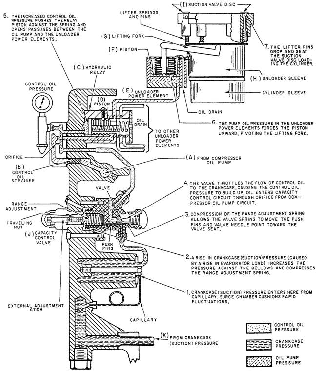
Figure 10-6.-Capacity control system.
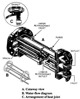
Several designs of capacity control systems are in use. One of the most common is shown in figure 10-6. The capacity control system consists of a power element and its link for each controlled cylinder, a step control hydraulic relay, and a capacity control valve. The system's components are all integrally attached to the compressor. The suction or crankcase pressure of the refrigeration plant is sensed by the capacity control valve to control the system. In other words, a change in the refrigeration load on the plant will cause a change in suction pressure. This change in suction pressure will then cause the capacity control system to react according to whether the suction pressure increased or decreased. The working fluid of the system is compressor oil pump pressure. Compressor oil pump pressure is metered into the system through an orifice. Once the oil passes the orifice, it becomes the system control oil and does work. Locate the following components or figure 10-6 and refer to them as you read the next two paragraphs. (A) Compressor oil pump pressure tap-off (B) Control oil strainer (C) Hydraulic relay (D) Hydraulic relay piston (E) Unloader power element (F) Unloader power element piston (G) Lifting fork (H) Unloader sleeve (I) Suction valve (J) Capacity control valve (K) Crankcase (suction) pressure sensing point The following functions take place when the compressor is started with a warm load on the refrigeration system. Compressor oil (A) is pumped through the control oil strainer (B) into the hydraulic relay (C). There the oil flow to the unloader power elements is controlled in steps by the movement of the hydraulic relay piston (D). As soon as pump oil pressure reaches a power element (E), the piston (F) rises, the lifting fork (G) pivots, and the unloader sleeve (H) lowers, permitting the suction valve (1) to seat. The system is governed by suction pressure, which actuates the capacity control valve (J). This valve controls the movement of the hydraulic relay piston by metering the oil bleed from the control oil side of the hydraulic relay back to the crankcase. Suction pressure increases or decreases according to increases or decreases in the refrigeration load requirements of the plant. After the temperature pulldown period with a subsequent decrease in suction pressure, the capacity control valve moves to increase the control oil bleed to the crankcase from the hydraulic relay. There is a resulting decrease in control oil pressure within the hydraulic relay. This decrease allows the piston to be moved by spring action. This action successively closes oil ports and prevents compressor oil pump pressure from reaching the unloader power elements. As oil pressure leaves a power element, the suction valve rises and that cylinder unloads. With an increase in suction pressure, this process is reversed, and the controlled cylinders will load in succession. The loading process is detailed in steps 1 through 7 in figure 10-6. Condenser The compressor discharges the high-pressure, high-temperature refrigerant vapor to the condenser, where it flows around the tubes through which seawater is being pumped. As the vapor gives up its superheat (sensible heat) to the seawater, the temperature of the vapor drops to the condensing point. The refrigerant, now in liquid form, is subcooled slightly below its condensing point. This is done at the existing pressure to ensure that it will not flash into vapor. A water-cooled condenser for an R- 12 refrigeration system is shown in figure 10-7. Circulating water is obtained through a branch connection from the fire main or by means of an individual pump taking suction from the sea. The purge connection (fig 10-7) is on the refrigerant side. It is used to remove air and other noncondensable gases that are lighter than the R-12 vapor. Most condensers used for naval refrigeration plants are of the water-cooled type. However, some small units have air-cooled condensers. These consist of tubing with external fins to increase the heat transfer surface. Most air-cooled condensers have fans to ensure positive circulation of air around the condenser tubes. Receiver The receiver (fig 10-8) acts as a temporary storage space and surge tank for the liquid refrigerant. The receiver also serves as a vapor seal to keep vapor out of the liquid line to the expansion valve. Receivers are constructed for either horizontal or vertical installation.
Figure 10-7.-Water-cooled condenser for an R-12 refrigeration system. |
 
|
|
|
||
|
|
Integrated Publishing, Inc. - A (SDVOSB) Service Disabled Veteran Owned Small Business
|