| Tweet |

Custom Search
|
|
 
|
||
|
ACCESSORIES In addition to the five main components of a refrigeration system, a number of controls and accessories are required. The most important of these are described briefly in the following paragraphs.
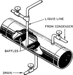
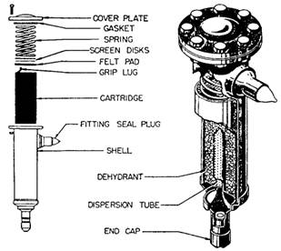
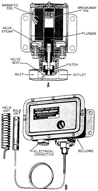
Figure 10-8.-Receiver. Dehydrator A dehydrator, or dryer, containing silica gel or activated alumina, is placed in the liquid refrigerant line between the receiver and the TXV. In older installations, bypass valves allow the dehydrator to be cut in or out of the system. In newer installations, the dehydrator is installed in the liquid refrigerant line without any bypass arrangement. A dehydrator is shown in figure 10-9 Moisture Indicator A moisture indicator is located either in the liquid refrigerant line or built into the dehydrator. The moisture indicator contains a chemically treated element that changes color when there is an increase of moisture in the refrigerant. The color change is reversible and changes back to a DRY reading when the moisture is removed from the refrigerant. Excessive moisture or water will damage the moisture indicator element and turn it gray, which indicates it must be replaced. Solenoid Valve and Thermostatic Control Switch A solenoid valve is installed in the liquid line leading to each evaporator. Figure 10-10 shows a solenoid valve and the thermostatic control switch that operates it. The thermostatic control switch is connected by long flexible tubing to a thermal control bulb located in the refrigerated space. When the temperature in the refrigerated space drops to the desired point, the thermal control bulb causes the thermostatic control switch to
Figure 10-9.-Refrigeration dehydrator.
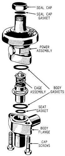
Figure 10-10.-Solenoid valve and thermostatic control switch. open. This action closes the solenoid valve and shuts off all flow of liquid refrigerant to the TXV. When the temperature in the refrigerated space rises above the desired point, the thermostatic control switch closes, the solenoid valve opens, and liquid refrigerant once again flows to the TXV. The solenoid valve and its related thermostatic control switch maintain the proper temperature in the refrigerated space. You may wonder why the solenoid valve is necessary if the TXV controls the amount of refrigerant admitted to the evaporator. Actually, the solenoid valve is not necessary on units that have only one evaporator. In systems that have more than one evaporator and where there is wide variation in load, the solenoid valve provides additional control to prevent the spaces from becoming too cold at light loads. In addition to the solenoid valve installed in the line to each evaporator, a large refrigeration plant usually has a main liquid line solenoid valve installed just after the receiver. If the compressor stops for any reason except normal suction pressure control, the main liquid solenoid valve closes. This prevents liquid refrigerant from flooding the evaporator and flowing to the compressor suction. Extensive damage to the compressor can result if liquid is allowed to enter the compressor suction. Evaporator Pressure Regulating Valve In some ships, several refrigerated spaces of varying temperatures are maintained by one compressor. In these cases, an evaporator pressure regulating valve is installed at the outlet of each evaporator EXCEPT the evaporator in the space in which the lowest temperature is to be maintained. The evaporator pressure regulating valve is set to keep the pressure in the coil from falling below the pressure corresponding to the lowest evaporator temperature desired in that space. The evaporator pressure regulating valve is used * on water coolers, * on units where high humidity is required (such as fruit and vegetable stow spaces), and * in installations where two or more rooms are maintained at different temperatures by the use of the same refrigeration unit. A cross section of a common evaporator pressure regulating valve (commonly called the EPR valve) is shown in figure 10-11. The tension of the spring above the diaphragm is adjusted so that when the evaporator coil pressure drops below the desired minimum, the spring will shut the valve. The EPR valve is not really a temperature control; that is, it does not regulate the temperature in the space. It is only a device to prevent the temperature from becoming too low. Low-Pressure Cutout Switch The low-pressure cutout switch is also known as a suction pressure control switch. This switch is the control that causes the compressor to go on or off as required for normal operation of the refrigeration plant.
Figure 10-1l.-Exploded view of a typical evaporator pressure regulating valve. It is located on the suction side of the compressor and is actuated by pressure changes in the suction line. When the solenoid valves in the lines to the various evaporators are closed, the flow of refrigerant to the evaporators is stopped. This action causes the pressure of the vapor in the compressor suction line to drop quickly. When the suction pressure has dropped to the desired pressure, the low-pressure cutout switch stops the compressor motor. When the temperature in the refrigerated spaces rises enough to operate one or more of the solenoid valves, refrigerant is again admitted to the cooling coils. This causes the compressor suction pressure to buildup again. At the desired pressure, the low-pressure cutout switch closes, starting the compressor, and the cycle is repeated again. High-Pressure Cutout Switch A high-pressure cutout switch is connected to the compressor discharge line to protect the high-pressure side of the system against excessive pressures. The design of this switch is essentially the same as that of the low-pressure cutout switch. However, the low-pressure cutout switch is made to CLOSE when the suction pressure reaches its upper normal limit, while the high-pressure cutout switch is made to OPEN when the discharge pressure is too high. As you already have learned, the low-pressure cutout switch is the compressor control for the normal operation of the plant. On the other hand, the high-pressure cutout switch is a safety device only. It does not have control of the compressor under normal conditions. Water Failure Switch A water failure switch stops the compressor if there is a circulating water supply failure. The water failure switch is a pressure-actuated switch. Its operation is similar to the low- and high-pressure cutout switches previously described. If the water failure cutout switch fails to function, the refrigerant pressure in the condenser quickly builds up to the point that the high-pressure switch stops the compressor. Strainer Because of the solvent action of R-12, any particles of grit, scale, dirt, or metal that the system may contain are circulated through the refrigerant lines. To avoid damaging the compressor from foreign matter, a strainer is installed in the compressor suction connection. Water Regulating Valve A water regulating valve controls the quantity of circulating water flowing through the refrigerant condenser. The water regulating valve is actuated by the refrigerant pressure in the compressor discharge line. This pressure acts upon a diaphragm (or, in some valves, a bellows arrangement) that transmits motion to the valve stem. The primary function of the water regulating valve is to maintain a constant refrigerant condensing pressure. Basically, the following two variable conditions exist: 1. The amount of refrigerant to be condensed 2. Changing water temperatures The valve maintains a constant refrigerant condensing pressure by controlling the water flow through the condenser. By sensing the refrigerant pressure, the valve permits only enough water through the condenser to condense the amount of refrigerant vapor coming from the compressor. The quantity of water required to condense a given amount of refrigerant varies with the water temperature. Thus, the flow of cooling water through the condenser is automatically maintained at the rate actually required to condense the refrigerant under varying conditions of load and temperature. Pressure Gauges and Thermometers A number of pressure gauges and thermometers are used in refrigeration systems. Figure 10-12 shows a compound R-12 gauge. The temperature markings on this gauge show the boiling point (or condensing point) of the refrigerant at each pressure; the gauge cannot measure temperature directly. The red pointer is a stationary marker that can be set manually to indicate the maximum working pressure. A water pressure gauge is installed in the circulating water line to the condenser to indicate failure of the circulating water supply. Standard thermometers of appropriate range are provided for the refrigerant system. |
||
|
||