| Tweet |

Custom Search
|
|
 
|
||
|
Sliding Spool Valve The sliding spool four-way directional control valve is similar in operation to the two-way valve previously described in this chapter. It is simple in its principle of operation and is the most durable and trouble-free of all four-way directional control valves.The valve described in the following paragraphs is a manually operated type. The same principle is used in many remotely controlled directional control valves.The valve (fig. 6-34) consists of a valve body containing four fluid portspressure (P),
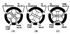
Figure 6-33.Operation of a rotary spool, four-way directional control valve.
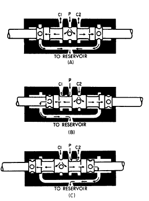
Figure 6-34.Operation of a sliding spool, four-way directional control valve. return/exhaust (R), and two cylinder ports (C/1 and C2). A hollow sleeve fits into the main bore of the body. There are O-rings placed at intervals around the outside diameter of the sleeve. These O-rings form a seal between the sleeve and the body, creating chambers around the sleeve. Each of the chambers is lined up with one of the fluid ports in the body. The drilled passage in the body accounts for a fifth chamber which results in having the two outboard chambers connected to the return/exhaust port. The sleeve has a pattern of holes drilled through it to allow fluid to flow from one port to another. A series of holes are drilled into the hollow center sleeve in each chamber.The sleeve is prevented from turning by a sleeve retainer bolt or pin which secures it to the valve body.The sliding spool fits into the hollow center sleeve. This spool is similar to the spool in the two-way valve, except that this spool has three pistons or lands. These lands are lapped or machine fitted to the inside of the sleeve. One end of the sliding spool is connected to a handle either directly or by mechanical linkage to a more desirable location. When the control handle is moved, it will position the spool within the sleeve. The lands of the spool then line up different combinations of fluid ports thus directing a flow of fluid through the valve. The detent spring is a clothespin-type spring, secured to the end of the body by a spring retaining bolt. The two legs of the spring extend down through slots in the sleeve and fit into the detents. The spool is gripped between the two legs of the spring. To move the spool, enough force must be applied to spread the two spring legs and allow them to snap back into the next detent, which would be for another position. Figure 6-34, view A, shows a manually operated sliding spool valve in the neutral position. The detent spring is in the center detent of the sliding spool. The center land is lined up with the pressure port (P) preventing fluid from flowing into the valve through this port. The return/exhaust port is also blocked, preventing flow through that port. With both the pressure and return ports blocked, fluid in the actuating lines is trapped. For this reason, a relief valve is usually installed in each actuating line when this type of valve is used.Figure 6-34, view B, shows the valve in the working position with the end of the sliding spool retracted. The detent spring is in the outboard detent, locking the sliding spool in this position. The lands have shifted inside the sleeve, and the ports are opened. Fluid under pressure enters the sleeve, passes through it by way of the drilled holes, and leaves through cylinder port C2. Return fluid, flowing from the actuator enters port C1, flows through the sleeve, and is directed out the return port back to the reservoir or exhausted to the atmosphere. Fluid cannot flow past the spool lands because of the lapped surfaces.Figure 6-34, view C, shows the valve in the opposite working position with the sliding spool extended. The detent spring is in the inboard detent. The center land of the sliding spool is now on the other side of the pressure port, and the fluid under pressure is directed through the sleeve and out port C1. Return fluid flowing in the other cylinder port is directed to the drilled passage in the body. It flows along this passage to the other end of the sleeve where it is directed out of the return/exhaust port.The directional control valves previously discussed are for use in closed-center fluid power systems. Figure 6-35 shows the operation of
Figure 6-35.Open center, sliding spool directional control valve. a representative open-center, sliding spool directional control valve. When this type of valve is in the neutral position (fig. 6-35, view A), fluid flows into the valve through the pressure port (P) through the hollow spool, and return to the reservoir. When the spool is moved to the right of the neutral position, view B, one working line (C1) is aligned to system pressure and the other working line (C2) is open through the hollow spool to the return port. View C shows the flow of fluid through the valve with the spool moved to the left of neutral |
||
|
||