| Tweet |

Custom Search
|
|
 
|
||
|
CHAPTER 3 POWER TRAIN AND PROPULSION SYSTEMS As a GS supervisor, you will primarily supervise the operation and maintenance of the power train equipment and controllable pitch propeller systems. This chapter will focus on the maintenance and repair of the main propulsion systems needed to support the operations of the main propulsion gas turbine engines. After studying the information in this chapter, you should have a well-rounded understanding of the drive train equipment and propulsion plant systems in gas turbine-powered ships. You should better understand terms of normal operations, some common malfunctions, and your role as the GS supervisor. POWER TRAIN In Gas Turbine Systems Technician (Electrical) 3/ Gas Turbine Systems Technician (Mechanical) 3, volume 1, NAVEDTRA 10563, there is a fairly detailed description of the various power train arrangements used by gas turbine-powered ships. You may wish to review those chapters on such items as construction, principles of operation, nomenclature, and operating parameters. In this section, we will cover some of the power train system tests, inspections, adjustments, and repairs that you will be responsible for as a supervisor. MAIN REDUCTION GEAR The inspection procedures and problems that occur in main reduction gears (MRGs) are basically the same for any system. It will not be necessary to differentiate between classes of ships in this section, except where specific differences exist. Additional information on the inspection and adjustment of gear trains can be found in Naval Ships' Technical Manual (NSTM), chapter 9420, "Propulsion Reduction Gears, Couplings, and Associated Components," NAVSEA 0901-LP-420- 0002, or in the manufacturer's technical manual for your specific installation. Inspection and Repair Before reading descriptions and details on MRG inspections, you need to be familiar with the terminology used throughout this section. The majority of the following gear nomenclature also applies to helical gears.
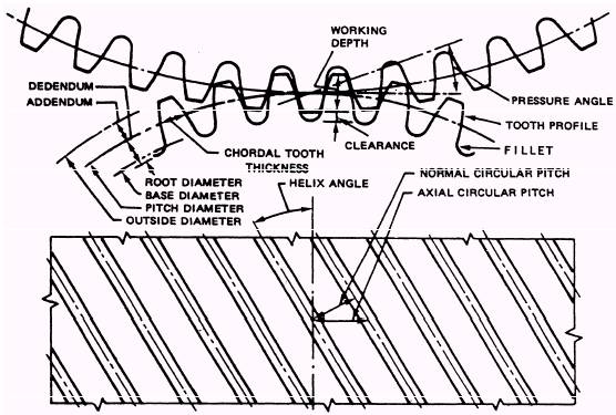
Figure 3-1 may be of help on some of these definitions. RATIO. The number of gear teeth divided by the number of teeth in the pinion. LINE OF ACTION. The locus of the points of contact as the profiles go through mesh. This line passes through the pitch point and is tangent to the base circle. HELIX ANGLE (fig. 3-l). The angle formed by a tooth and a plane passing through the axis of the gear. PRESSURE ANGLE (fig. 3-1). The angle between the line of action and the line tangent to the pitch circles. TRANSVERSE DIAMETRAL PITCH. The ratio of the number of teeth to the number of inches of the pitch diameter. NORMAL DIAMETRAL PITCH. The transverse diametral pitch divided by the cosine of the helix angle. CHORDAL TOOTH THICKNESS (normal) (fig. 3-1). The thickness of the tooth measured on the chord of the pitch diameter in the normal plane. CIRCULAR PITCH (axial) (fig. 3-l). The length of the arc on the pitch circle between similar points of adjacent teeth in the plane of rotation. CIRCULAR PITCH (normal) (fig. 3-l). The length of the arc on the pitch circle between similar points of adjacent teeth in the normal plane. OUTSIDE DIAMETER (fig. 3-l). The diameter measured over the tops of the teeth. PITCH DIAMETER (fig. 3-l). The diameter of the pitch circle. BASE DIAMETER (fig. 3-l). The circle from which a line is unwound to generate the involute curve. ROOT DIAMETER (fig. 3-1). The diameter of the root circle. ADDENDUM (fig. 3-1). The distance from the pitch circle to the top of the tooth. DEDENDUM (fig. 3-1). The distance between the pitch circle and the bottom of the tooth space. WORKING DEPTH (fig. 3-1). The depth to which the teeth of a gear enter into their mating space. CLEARANCE (root) (fig. 3-1). The distance between the top of a tooth and the bottom of its mating space. WHOLE DEPTH. The total depth of the tooth space and also the sum of the addendum and dedendum. INTERFERENCE. Contact between mating gears at some point other than along the line of action. FILLET (fig. 3-l). The concave radius that joins the tooth profile and the bottom of the tooth space. Tests and inspections according to the PMS are minimum requirements only. When defects are suspected, or operating conditions indicate, inspections should be made at more frequent intervals. When opening gear cases for inspection, use extreme care. Even under normal conditions, when the covers are lifted the possibility of getting foreign particles inside the gear case is high. The engineer officer should evaluate all ongoing work in the engine room, especially in the areas over the gears. Besides evaluating the work, the engineer officer must schedule all necessary MRG inspections. You must be sure that gear sumps are cleaned after all work to the MRG has been completed. Thoroughly inspect the gear sump and remove any foreign material. Absolute cleanliness is required before filling the gear sump with clean oil. Oil should be renovated before returning it to the sump. If new oil is used, you must be careful to remove any water or foreign particles. Cloth bags placed in the lube oil (LO) strainer baskets after major repairs is another required precaution. The bags stop foreign particles from passing through the gear train and bearings. Once the proper temperatures and pressures have been reached in the LO system, inspect the MRG for leaks and all sight-flow indicators for proper flow. The following paragraphs discuss some of the inspections, tests, and problems that may occur to MRGs. |
 
|
|
|
||
|
|
Integrated Publishing, Inc. - A (SDVOSB) Service Disabled Veteran Owned Small Business
|