|
The model 5328A frequency counter can be divided into four major internal subsections:
the main counter section, input section, power supply, and interface bus section.
Additionally, two separate (front panel) input channels provide for time interval
measurements. Each channel has an attenuator, trigger slope selector, level control, ac or
dc coupling, and an oscilloscope marker output. A third input channel is provided to allow
the measurement of 30 MHz to 500 MHz with a maximum input of 5 volts rms with a
fused-protected connection.
Front-panel controls are provided for you to do the function selection, frequency
resolution, sample rate, and reset display. Also, a push-button control on the front panel
allows the unit to be used in the operational or standby mode (power applied to the
crystal oven to eliminate warm-up). Rear-panel connectors provide the gated output
frequencies and an input for an external frequency standard. A detachable front cover is
used to store accessory cables and connectors.
Controls and Indicators
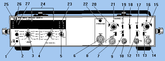
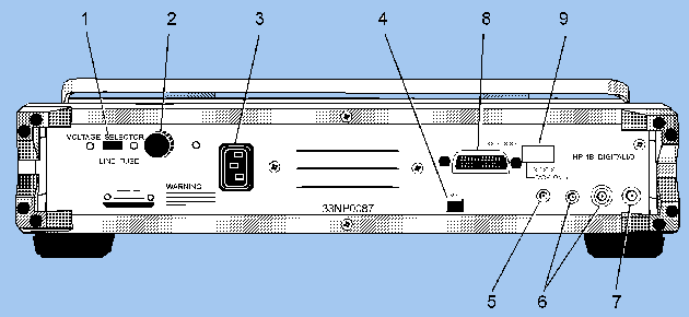
Figures 5-10 and 5-11 show all the front- and rear-panel operating controls and
indicators. Refer to tables 5-1 and 5-2 for a description of each of the numbered controls
and connectors shown in figures 5-10 and 5-11, respectively.
Figure 5-10. - Front-panel controls and indicators.

Figure 5-11. - Rear-panel controls and connectors.

Table 5-1. - Front Panel Controls and Connectors
| NO. |
NAME |
DESCRIPTION |
| 1 |
LINE switch |
This is a two-position switch that can be selected for STBY or OPER. When
in STBY, the power supply provides power to the oven of the high stability time base to
maintain a constant temperature for the crystal. When in OPER, the power supplies normal
power to the unit for operation. |
| 2 |
RESET |
This button, when pressed, resets the display and internal count to zero.
When pressed continuously, this button lights all segments of the LED display and all
annunciator LEDs for a LED test. |
| 3 |
FUNCTION |
This is a 10-position selector used to select the mode of operation. |
| |
FREQ A |
This position, when selected, allows the counter to measure frequency at
channel A. |
| |
FREQ C |
This position, when selected, allows the counter to measure the frequency
at channel C. |
| |
PER A |
This position, when selected, allows the counter to measure the period at
channel A. |
| |
PER AVG A |
This position, when selected, allows the counter to make a period average
measurement of the signal at channel A. The number of periods over which the average is
made is determined by the RESOLUTION switch selection. |
| |
T. I. AVG AB |
This position, when selected, allows the counter to make a time interval
measurement of a signal applied to channel A. The number of time intervals over which the
average will be made is determined by the RESOLUTION switch selection made. |
| |
T. I. AB |
This position, when selected, allows the counter to make a time interval
measurement. The start signal would be applied to channel A and the stop signal applied to
channel B. |
| |
CHECK |
This position, when selected, applies a 10-MHz signal to the decade
counting assemblies, verifying operation of the SAMPLE RATE control, RESOLUTION switch,
and RESET. |
| |
RATIO C/A |
This position, when selected, allows the counter to measure the ratio of
the frequency at channel C to the frequency at channel A. |
| |
RATIO B/A |
This position, when selected, allows the counter to measure the ratio of
the frequency at channel B to the frequency at channel A. |
| |
Top |
This position is blank and has no function. |
| 4 |
FREQ RESOLUTION, N |
This is an eight-position switch that is used to select the resolution in
frequency measurements and N for totalizing and averaging measurements. This also
determines how long the main gate is open for frequency measurements. |
| |
|
N |
GATE TIME
(seconds) |
RESOLUTION |
| |
|
1 |
1X10⁻⁶ |
1 M |
| |
|
10 |
10X10-6 |
100 k |
| |
|
102 |
100X10-6 |
10 k |
| |
|
103 |
1X10⁻³ |
1 k |
| |
|
104 |
.01 |
100 |
| |
|
105 |
.1 |
10 |
| |
|
106 |
1 |
1 |
| |
|
107 |
10 |
.1 |
| 5 |
SAMPLE RATE control |
This is used to vary the time between measurements continuously from
approximately 2 milliseconds to an indefinite hold of the display. |
| 6 |
500 MHz, 50W |
This is the channel C input connector. |
| 7, 14 |
OUTPUT MARKER |
These are the channel A and B Schmidt trigger outputs used to indicate
when a channel is triggered by 0 to 300 mV levels with less than 20 nanoseconds delay. |
| 8, 13 |
AC/DC |
These control the selection of ac or dc coupling for the input signal.
When the input amplifier control switch (No. 18) is in COM A, channel B coupling is
determined by setting of channel A coupling switch. |
| 9, 12 |
ATTEN switches |
These select the attenuation of the input signal. The signal amplitude is
reduced by 10 in X10 and by 100 in X100. When the input amplifier control switch (No. 18)
is in COM A, the channel B attenuation is determined by the channel A attenuation switch. |
| 10, 11 |
INPUT A and B |
These are the input BNC connectors for channels A and B. |
| 15, 20 |
LEVEL A/B |
These controls are used in conjunction with the ATTEN (Nos. 9, 12) to
select the voltage at which triggering will occur. With X1 attenuator selected, the level
is variable at 2.5
volts, X10 at 25 volts, and X100 at 250 volts. |
| 16, 21 |
Channel A and B triggering lights |
The light will blink for the associated channel when triggering is
occurring. When the light is off, the input signal is below triggering level and on when
the signal is above triggering level. |
| 17, 19 |
Channel A and B SLOPE switch |
These switches control the selection of triggering on either the positive
or negative slope of the input signal. |
| 18 |
COM A/SEP |
This is the input amplifier control switch that selects independent
operation of channels A and B in SEP (separate) position. When in COM A (common A)
position, the signal at A is also applied to channel B; this disconnects the channel B
input circuitry. Channel B coupling and attenuation are then determined by the channel A
setting. |
| 22 |
OVERLOAD |
This indicator will flash on and off if more than 5 volts is applied to
channel C input. |
| 23 |
K, S, M, n m and Hz |
These will light up to show the appropriate units multiplier of the
measurement being taken. |
| 24 |
LED display |
This is a nine-digit LED display that shows the numerical measurement
taken. |
| 25 |
OVFL |
This indicates an overflow of one or more of the most significant digits
(leftmost from the decimal point) are not displayed. |
| 26 |
RMT |
Lights when the unit is in remote operation. |
| 27 |
GATE |
Lights when the counter's main gate is open and a measurement is in
progress. |
Table 5-2. - Rear-Panel Controls and Connectors
| NO. |
NAME |
FUNCTION |
| 1 |
VOLTAGE SELECTOR |
Used to select 115 or 230 volt operation. |
| 2 |
LINE FUSE |
This requires the insertion of a 2.0 amp fuse for 115 volt or 1.0 amp fuse for 230
volt operation. |
| 3 |
Input ac connector |
Used to connect the input ac to the unit. |
| 4 |
ARM |
When this switch is in the OFF position, the counter is armed by the signal that is
selected for measurement. In the ON position, the measurement is armed by an input other
than the input being measured. |
| 5 |
EXT OSC |
Tgis input connector allows a separate outside signal to be used for the time base. |
| 6 |
1 MHz OUT and 10 MHz OUT |
These connectors allow an internal oscillator signal to be used externally when
connected. |
| 7 |
GATE/MARKER OUT |
Applies a high to the output when the main gate is open. |
| 8 |
HP-IB |
This is an interface bus connector that allows the unit to receive programming
instructions. |
| 9 |
HP-IB address |
This switch is used to allow the proper addressing for the interface bus. |
Frequency Measurement
As discussed previously, the model 5328A frequency counter is capable of measuring
frequency, time period (inverse of frequency), ratio, and time interval. We will start
with frequency. When the FUNCTION selector is in the FREQ A or FREQ C position, the
counter measures the frequency, f, by accumulating the number of cycles, n, of the input
signal that occurs over the time period, t. This is expressed by:

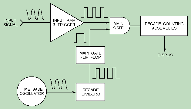
The basic counter elements necessary to perform this measurement are shown in figure
5-12. The INPUT AMPLIFIER/TRIGGER essentially conditions the input signal to a format that
is compatible with the internal circuitry of the counter. As figure 5-12 indicates, the
output of the amplifier/trigger corresponds directly to the input signal.
Figure 5-12. - Basic elements of the frequency counter.

The TIME BASE OSCILLATOR is a 10-MHz temperature-controlled (oven-regulated) precision,
crystal oscillator used for the time base element from which time, t, is derived. DECADE
DIVIDERS take the time base oscillator signal as the input and provide a pulse train,
whose frequency is variable in decade steps. This frequency can be controlled by the FREQ
RESOLUTION, N switch. The time, t, is determined by the period of this pulse train.
The heart of the counter is the MAIN GATE. When the gate is opened, pulses from the
amplifier/trigger are allowed to pass through. The opening and closing of the main gate is
controlled by the decade divider output to the main gate flip-flop. The output of the MAIN
GATE is then sent to the DECADE COUNTING ASSEMBLIES (DCAs), where the pulses are combined
and displayed after the gate is closed.
If the FREQUENCY RESOLUTION, N selection switch, is set for 106, the main
gate is open for 1 second, and the decade counting assemblies display the frequency of the
input signal in hertz (refer to figure 5-10, FREQUENCY RESOLUTION, N selection switch).
|

|


