Custom Search
|
|
 
|
||
|
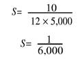
SCALE OF THE FINISHED MOSAIC MAP The scale of the finished mosaic map is determined by using the following formula:
Where S= Scale F = Lens focal length A = Altitude The answer derived by using this formula gives a representative fraction (RF) in like-units. Notice that you must convert the altitude to inches, since the lens focal length is normally in inches. For example, you used a 10-inch focal-length lens for a mapping mission flown at 5,000 feet. You can determine the scale of the finished mosaic as follows:
The scale of the finished mosaic is 1/6,000 (1:6,000). To reinforce the mission planning procedures, you can use the following example: You are assigned to assist in the mission calculations required for a recon mapping mission. You are briefed on the mission and the following information is provided: Area to be mapped is 10 nautical miles east and west by 20 nautical miles north and south. Forward overlap required is 60 percent. Side lap required is 40 percent. Lens focal length is 12 inches. Negative size is 9 x 9 inches. True airspeed of aircraft is 140 knots. The wind is from the north at 15 knots. The scale of the chart used to plan and fly the mission is 1/50,000 (1:50,000). The required scale is 1/12,000 (1: 12,000). A graphic scale representing 3,000 feet is required on the printed mosaic map. 1. Determine the altitude. The first step in this problem is to determine the altitude at which the aircraft must fly to obtain the required scale of 1/12,000. The IFGA formula used to determine the altitude is as follows:
Since G (ground coverage) is not known, you must substitute the required scale (1/12,000) for it. At a required scale of 1/12,000, each unit of I (on the film plane) records 12,000 units of G. Since A is measured in feet, you must divide your answer by 12 to get the units in feet.
Divide by 12 to get altitude units in feet 144,000/12 = 12,000 feet 2. Determine the ground coverage. Now that you know the altitude at which the mission must be flown to obtain a scale of 1/12,000, you can determine the amount of ground coverage on each frame. Again, this information can be determined using the IFGA formula. Remember that the forward overlap required is 60 percent. The remaining 40 percent of the 9-inch negative is usable imagery for GGF. You must first find the size of the usable portion of the negative for GGF. This is accomplished as follows: 0.40 x 9 = 3.6 inches of useable image area for GGF
The amount of side lap required is 40 percent. This leaves only 60 percent of the useable negative image area for GGS. You determine the usable portion of the negative for GGS as follows: 0.60 x 9 = 5.4 inches of usable image area for GGS
3. Determine the total number of frames required. Next, you need to determine the total number of frames required to complete the mission. You know that the area to be mapped is 10 nautical miles east and west by 20 nautical miles north and south. Therefore, the strips will be flown north and south. The number of exposures per strip is determined by dividing the GGF into the length of the map. First convert nautical miles into feet (1 nmi = 6,080 ft) and multiply by 20 (length of area to be mapped). 6,080 x 20 = 121,600 feet Next, divide by the GGF as follows: 121,600/3600 = 33.77 or 34 frames per strip. Remember to add four more frames. This totals 38 frames for each strip. Now you must find the number of strips required. The area to be mapped is 10 nautical miles long. Calculate the number of strips as follows: 10 (nautical miles) x 6,080 (feet per nautical mile) = 60,800 feet 60,800/5400 (GGS) = 11.25 or 12 flight strips Remember to add one strip, so a total of 13 flight strips is required. To determine the total frames required for the mapping mission, you must multiply the number of frames required for GGF by the number of flight strips required as follows: 13 x 38 = 494 frames 4. Draw flight lines on the chart. Your next step is to draw the flight lines on the chart used to fly the mission. The scale of this chart is 1/50,000. To determine the distance between the plotted lines on the chart, you must convert the GGS into inches, and then multiply the GGS (in inches) by the scale of the chart as follows: 5,400 (feet) x 12 = 64,800 (inches) x 1/50,000 = 1.29 inches The distance between flight lines on the chart is 1.29 inches apart. A multi-finger divider should be used to draw these lines. 5. Determine the time interval between exposures. To determine the exposure interval, first convert the aircraft speed to feet per second. The true aircraft speed is operating at 140 knots, but there is a wind of 15 knots coming from the north. Since the aircraft will be flying in a north and south direction, the wind factor must be taken into consideration. At this time determine the corrected airspeed in knots, then determine the airspeed in feet per second as follows: 1. Corrected airspeed. a. Aircraft flying toward the north Corrected airspeed (140 knots - 15 knots = 125 knots) b. Aircraft flying toward the south Corrected airspeed (140 knots + 15 knots = 155 knots) 2. To determine aircraft speed in feet per second, you must multiply the corrected airspeed by the conversion factor of 1.7. a. Aircraft flying toward the north = 212.5 feet per second b. Aircraft flying toward the south = 263.5 feet per second To calculate the exposure interval, you must use the following formula:
T = Time in seconds D = GGF (distance) S = Ground speed in feet per second By substituting the values, you can determine the exposure intervals as follows:
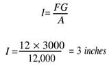
6. Graphic scale. To determine what graphic scale represents 3,000 feet, you should use the IFGA formula as follows:
Therefore, 3 inches on the map represents 3,000 feet on the ground. |
 
|
|
|
||