|
||
|
|
||
| |||||||||||||||
|
|
SIZING DUCT SYSTEMS There are numerous factors to be considered when sizing duct systems. These factors cause you to make modifications and adjustments throughout the planning and installation process to develop an efficient working system. First, you must calculate the air volume required for heating and for cooling the required space. This will assist you in determining the necessary duct size, fan size, fan speed, and so forth, that is needed to circulate the conditioned air. While determining the heating and the cooling factors, you should think in terms of air circulation throughout the building and in each individual room or space. Remember, air movement is determined by the type of return airflow that you use. Four other important duct system components are diffusers, grilles, registers, and dampers. Each of these components has a direct correlation between functional design, amount of air accommodated, and the air movement pattern. The elbows within the duct system are a major source of airflow restriction. Whenever possible, you can gain efficiency by installing long sweeping elbows. Short 90-degree elbows should be used sparingly on long duct runs. However, they can be used very effectively with a minimum of air turbulence and airflow restriction when installed just before diffusers, grilles, and registers. Your final duct calculations involve taking unit pressure drops and total pressure drops throughout the system. Some of the major contributing factors to these pressure drops are as follows: . Length of duct . Duct material and interior finish . Changes in duct size . Number of elbows
Normally, you will be installing a duct system according to preestablished blueprints and drawings. Occasionally you may need to refer to other sources and review trade association standards. The ASHRAE Handbook of Fundamentals has three chapters dedicated to methods and procedures for selecting proper duct sizes. You should become familiar with the contents of these three chapters; particularly, if you are involved in the design phase of an air-conditioning system. BALANCING DUCT SYSTEMS A duct system is always installed to fulfill specific requirement features related in some way to the health and welfare of human beings. Equally important is the fact that a properly balanced operating system results in lower operating costs and significant utilities conservation. Consequently, it is important that these systems, regardless of the function, operate properly. When a duct system is initially installed, the required pressures and performance data are available from the construction drawings and the manufacturer's instructions. After installation, pressures and performance requirements should be measured to ensure proper airflow at different locations. Once the proper airflows are established, little change should take place within the system. Maintenance personnel must ensure that the system is operating correctly by conducting certain periodic tests. Tests are used for the initial and subsequent setting of grilles, diffusers, dampers, and registers to obtain the necessary airflow required by specifications, codes, regulations, or trade association standards. It is important to understand the pressure in a duct carrying a moving stream of air. Certain changes in an existing duct system are often necessary and you should be able to accomplish these changes. In addition, malfunctioning duct systems require immediate attention, and an understanding of the basic elements of the system is required before troubleshooting and corrective action can be undertaken. Furthermore, before a duct system can be properly balanced, certain essential knowledge of airflow is required. Static pressure is a measure of the outward push of air on the walls of a duct. When air is not moving within a duct because a damper at the outlet is closed, the static pressure can be measured by means of a pressure gauge installed in the wall of the duct. If the damper in the duct is then opened and the air is flowing, static pressure continues to be present. It will be reduced when the damper is opened, but the static pressure can still be read on the gauge. When air is flowing in a duct, there is another pressure-in addition to the static pressure-that can be measured. This is the pressure exerted by the moving airstream. This pressure acts in a plane perpendicular to the direction of airflow. To illustrate, imagine a horizontal duct without any air flowing in it. When a thin, flat piece of metal is suspended with a movable hinge from the top of the duct, it will hang straight down when air is not moving. When air flows, the hinged piece of metal swings upward toward the top of the duct. The velocity pressure is the force that causes the deflection of the hinged vane (obviously, the greater the air velocity, the greater the pressure acting on the hinged vane and the greater its deflection from the perpendicular). The velocity pressure cannot be measured as easily as the static pressure. When a hollow tube is inserted in the moving airstream, and a gauge is connected to the end of the tube, the gauge registers a certain pressure. This pressure is larger than the static pressure because the gauge indicates the sum of the static and the velocity pressure. This sum is known as the total pressure. Since
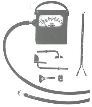
Figure 13-4.-Velometer set.
Figure 13-5.-Pitot probe. total and static pressure can be easily measured, the velocity pressure can be found by subtracting static from total pressure. In most problems concerning duct systems, air pressure is expressed in terms of inches of water (1 pound per square inch = 27.74 inches of water.) At the time of initial installation of a duct system, the design data should be recorded. After initial start-up, the system should be balanced so that each air outlet is adjusted to the design rate of flow. During the initial balancing procedure, the actual design rate of flow is sometimes not achieved, but the flow is within the range of acceptable standards. When such conditions exist, they should be noted on the design data sheet where they may be considered by maintenance personnel during repairs or the rebalancing of the system. After the system is balanced and proper operation is assured, static pressure measurements are taken throughout the system. Also, the total pressure difference across the fan (the difference between the suction total pressure and the discharge total pressure) is noted. Although these initial measurements can be used for checking the design of the system, their main function is to serve as reference data for future tests. If the system fails to function properly at any time, another set of measurements should be taken and compared to the original set. |
|
Privacy Statement - Press Release - Copyright Information. - Contact Us - Support Integrated Publishing |