|
||
|
|
||
| |||||||||||||||
|
|
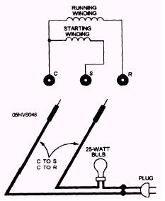
Voltmeter Test Procedure The procedure for carrying out a voltmeter test is as follows: Ensure the power is on and all wires are properly connected to motor terminals. With the voltmeter set on the proper scale, place the leads across the R- and C-terminals. Read the voltmeter.If the motor shows line voltage, the motor is energized and should be operating. The connections are similar to that shown in figure 14-31. Test Lamp Continuity Check Procedure The procedure for conducting a test lamp continuity check is as follows: A simple test lamp consisting of a power circuit plug, two flexible insulated wires with clip leads, and a 25-watt socket with a bulb is used. Figure 14-32 shows the test lamp procedure. Ensure the power is OFF, discharge all capacitors, and remove the motor terminal wires. Make a continuity test through both windings by attaching clips across the C-terminal, then do the other terminals one at a time. Now plug the test lamp into a receptacle. If the bulb fails to light, there is an open winding. SHORTED WINDINGS In an electric motor the winding turns lie side by side with only the insulating varnish separating one loop from another. When one loop of the copper wire contacts another, the
Figure 14-32.-Testing for an openwinding with a test lamp.
winding is short. The pulling effect of the shorted portion of the winding is lost. This, in turn, places more load on the active winding, causing the motor to draw higher voltage and amperage with a concurrent increase in winding temperature. In this condition the motor either fails to start, or it starts and continues to run, finally causing the overload protector to open. The fuses may also blow. The result is likely to be a burnout where the insulating varnish deteriorates from excessive heat. Ultimately a ground or short occurs. An ohmmeter can be used to check windings for shorts. For most applications a low-range meter with a scale graduated in tenths of ohms between 0 and 2 ohms is best. However, to check motors throughout the sizes normally encountered in hermetic motor-compressor units, a range of 0 to 25 ohms is necessary. The meter is used to measure resistance of the windings. The readings are compared with design resistances. A short is shown when measured resistance is less than design resistance. The ohmmeter connections are the same as those shown in figure 14-30. Often manufacturer's data is not available and the design resistances are not known. Table 14-1 lists the approximate resistances for fractional horsepower single-phase motors. The following guidelines may also be helpful: 1. The starting winding of low-starting torque motors usually has a resistance of about seven to eight times that of the running winding. 2. The starting winding resistance of high- starting torque motors is usually three to four times that of the running winding. |
|
Privacy Statement - Press Release - Copyright Information. - Contact Us - Support Integrated Publishing |
|
|
Integrated Publishing, Inc. - A (SDVOSB) Service Disabled Veteran Owned Small Business
|