|
||
|
|
||
| |||||||||||||||
|
|
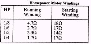
GROUNDED WINDINGS A ground is the result of an electrical conductor in contact, either directly or indirectly, with the motor frame or the metal Table 14-1.-Approximate Resistances for Fractional
shell of the unit. Either the starting winding, the running winding, or both can be affected. The ground is either one of low resistance or one of high resistance. A low-resistance ground is indicated when fuses blow repeatedly and the motor fails to start. A high-resistance ground is shown by an occasional blown fuse, but more often, by the opening of the overload protector. Three methods of testing windings for grounds are the ohmmeter continuity test, the test lamp continuity check, and the resistance measurement with a megohmmeter. The procedure to follow in making each of these tests is provided below. Ohmmeter Continuity Test (Low-Resistance) Procedure To perform an ohmmeter continuity test, proceed as follows: Disconnect the power and remove the wires from the motor terminals. Scrape off paint and clean a spot on the motor-compressor shell for testing.
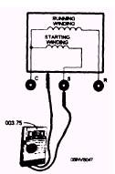
Figure 14-33.-Testing windings for ground with an ohmmeter. 14-20
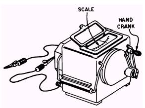
l With the ohmmeter set on its highest scale, test for continuity between the terminals and the shell. This procedure is shown in figure 14-33. If continuity exists between the terminals and the shell, there is a ground. Test Lamp Continuity Check (Low-Resistance) Procedure The procedure for conducting a test lamp continuity check is as follows: l Disconnect the power and remove the wires from the motor terminals. l Ensure the lamp is connected in the hot side of the line. Plug the test lamp into a receptacle. l Connect the hot-line probe to a motor winding terminal. l Touch the free probe to the cleaned spot on the shell. Ensure that a good connection is made. If the light illuminates, there is a grounded winding. Megohmmeter (High-Resistance) Test Procedure The megohmmeter (megger) consists of an indicating movement for which current is supplied by a small hand-driven generator. Figure 14-34 illustrates a typical megger used by the SEABEES.
Figure 14-34.-A typical megohmmeter (megger). Two leads are supplied, one of which is marked Earth or Ground. The procedure for making the megohmmeter (high-resistance) test is as follows: l Disconnect power and remove the wires from the motor terminals. l Place the megger probe marked Earth or Ground on the motor or compressor frame. Ensure there is a good metal-to-metal contact. l Place the free probe on terminals C, S, and R in sequence. If any reading of low resistance is obtained, the motor is grounded. You should always refer to the manufacturer's instructions when using a megger. It is also a good idea to request assistance from a Construction Electrician. |
|
Privacy Statement - Press Release - Copyright Information. - Contact Us - Support Integrated Publishing |
|
|
Integrated Publishing, Inc. - A (SDVOSB) Service Disabled Veteran Owned Small Business
|