|
||
|
|
||
| |||||||||||||||
|
|
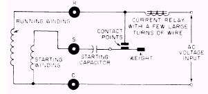
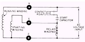
ELECTRICAL CIRCUIT COMPONENTS Electrical components in hermetic motor compressor circuits that give trouble include starting relays, overload protectors, and capacitors. It is essential that a refrigeration and airconditioning service member be able to identify these components and test them using the proper equipment and procedures. STARTING RELAYS Basically there are three types of starting relays in use. They are the current relay (magnetic type), the voltage relay (magnetic type), and the thermal relay (hot-wire type). In the hermetic motor control circuit, a starting relay allows electricity to flow through the starting winding until the motor reaches two-thirds to three-fourths of its rated speed. At this time, about 3 to 4 seconds after starting, it disconnects the starting circuit. Current Relay A current relay is an electromagnet, similar to a solenoid valve, that employs a weight and spring to hold the contacts open when the circuit is idle. In operation the instantaneous surge of starting current actuates the magnetic coil, causing the start winding contacts to close. This closure allows starting current to the winding; after about 3 to 4 seconds, the motor reaches its rated speed and the current decreases, causing the relay contact to open and disconnect the winding. Current relays are ideal for use with split-phase, induction-run motors. Figure 14-35 is a schematic diagram of a current relay motor starting circuit. Voltage Relay A voltage relay looks much like a current relay; however, it differs in operation. It operates on increased voltage as the motor reaches rated speed, and, unlike the current relay, the contacts remain closed during the off cycle. When the motor is first turned on, it draws heavy current and the voltage drop across the starting winding is low. As the motor picks up speed, there is less and less load; therefore, more and more voltage is induced into the winding. At about three-fourths rated speed the voltage is high enough to cause the relay coil to pull the contacts open and disconnect the winding. Voltage relays are used with
Figure 14-35.-Schematic diagram of a current relay motor starting circuit.
Figure 14-36.-Schematic diagram of a voltage relay motor starting circuit. capacitor-start motors. Figure 14-36 is a schematic diagram of voltage relay motor starting circuit. |
|
Privacy Statement - Press Release - Copyright Information. - Contact Us - Support Integrated Publishing |
|
|
Integrated Publishing, Inc. - A (SDVOSB) Service Disabled Veteran Owned Small Business
|