Custom Search
|
|
  |
|
|
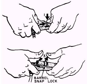
PREPARATION FOR USE When you receive an automatic parachute ripcord release from supply, there are some preparations for you to make before placing it into service. Upon removal of the ripcord release from the shipping carton, the exterior parts of the unit must be inspected for damage during shipping and storage. An inspection should be made for corrosion, dirt, dents, and cracks. If any damage or discrepancy is found, a quality deficiency report must be submitted, and a tag must be affixed to the ripcord release stating that it is not to be used. Remove this tag only after correction has been made. Fired ripcord release assemblies must not be reused. All Model 7000 automatic parachute ripcord release assemblies that fail any inspection points must have a tag affixed stating the nature of the defects. NOTE: Refer to NAVAIR 11-100-1.1 for the cartridge service life/total life. The cartridge service life must not expire prior to the next scheduled repack of the parachute assembly. WARNING YOU SHOULD EXERCISE EXTREME CAUTION WHEN HANDLING AUTO-MATIC RIPCORD RELEASE AS-SEMBLIES AFTER THE CARTRIDGE HAS BEEN INSERTED IN THE BAR-REL. DO NOT ALLOW EITHER END OF THE COVER ASSEMBLY TO BE POINTED TOWARD YOUR FACE AS HIGH VELOCITY FLAME AND SMOKE MAY BE PRODUCED IF THE CARTRIDGE GOES OFF. ANOTHER REASON FOR EXTREME CAUTION IS THE POSSIBILITY THAT THE PIS-TON OF THE RIPCORD RELEASE MAY BECOME A PROJECTILE IF THE CARTRIDGE ACCIDENTALLY FIRES. An automatic ripcord release in service must be inspected each time its parachute assembly is repacked. You must pay particular attention to detail when working on a automatic ripcord release. The importance of careful work must be impressed upon personnel actually performing the work, as well as those assigned to collateral duty inspections. You will find more detailed information concerning automatic parachute ripcord release assemblies in the Emergency Personnel and Drogue Parachute Systems Manual, NAVAIR 13-1-6.2, and the Maintenance Requirements Cards, NAVAIR 13-600-4-6-3. MAINTENANCE Maintenance on any automatic ripcord release in service must be performed each time its parachute assembly is repacked. Maintenance consists of the following: . Disarming . Inspection . Firing altitude check . Arming and assembly . Checkout of armed mechanism As you work on a automatic ripcord release assembly, you are required to perform several different types of maintenance and inspections. You are required to inspect the operational condition of the automatic ripcord release before installing it in a parachute assembly. If you find any damage or an inspection discrepancy, submit a quality deficiency report, as discussed in OPNAVINST 4790.2 (series). NOTE: Under no circumstances should an unsatisfactory ripcord release be installed. The first step in performing the normal inspection and maintenance on a automatic ripcord release is to disarm it. Then you are ready to inspect and perform the firing altitude checks. DISARMING Anytime you are required to disarm a ripcord release assembly, follow the procedures outlined in NAVAIR-13-1-6.2. The discussion that follows closely parallels those procedures. A parts breakdown can be seen in figure 2-1. NOTE: To remove the arming cable housing from the ripcord release, depress the safety retainer release (fig. 2-1). NEVER try to remove the arming cable from an armed ripcord release assembly by pulling on the cable. This fires the automatic ripcord release. 1. Open the ripcord release pocket, and remove the ripcord release only a sufficient distance to allow disassembly. 2. Remove the locking screw and washer. NOTE: The cover and power cable housing assembly and the receiver and barrel assembly are serialized matched sets. Do not mix these assemblies. 3. Slide the cover off the receiver and barrel assembly. 4. Disengage the barrel snap lock. A close-up of this operation is shown in figure 2-2. 5. Remove the cartridge from the barrel assembly (fig. 2-1). Do not proceed until the quality assurance inspector (QA) has verified this step. 6. Remove the ripcord release assembly and the arming cable housing from the parachute container.
Figure 2-2.-Disengaging barrel snap lock.
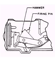
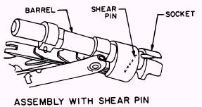
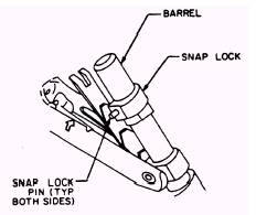
Figure 2-3.-Checking firing pin and hammer. INSPECTION To inspect the automatic ripcord release, proceed as follows: 1. Inspect the cover and power cable housing assembly for nicks, gouges, distortion, corrosion, and security of the power cable housing. 2. Inspect the power cable for freedom of movement, and secure attachment of the swaged ball and power cable eye. 3. Inspect the receiver and barrel assembly for excessive nicks, cracks, gouges, distortion, and corrosion or other damage that could cause a malfunction while in service. 4. Inspect the firing pin on the hammer for flattening, gouges, or other damage (fig. 2-3). 5. You must secure the arming pin by inserting the pin in the retainer while the barrel is unlocked. Press the pin firmly into place until it locks into the pin groove. The pin should now be held securely. Do not twist the socket as this will break the shear pin. NOTE: Early Model 7000 automatic parachute ripcord release assemblies use safety wire, as shown in figure 2-1. When inspecting these assemblies, check for security and the proper type of wire. 6. Inspect the socket for visible damage and retention of the socket and piston by a shear pin (figs. 2-1 and 2-4). 7. Inspect the snap lock pins for security and absence of damage (figs. 2-1 and 2-5). NOTE: If the tamper dot is broken, you need to torque the screw to a value of 14 1/2 to 15 1/2 inch-pounds and apply a new tamper dot.
Figure 2-4.-Checking for proper retention of socket by a shear pin.
Figure 2-5.-Checking for security of snap lock.
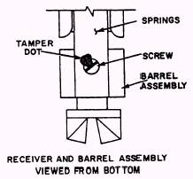
Figure 2-6.-Checking springs and tamper dot. 8. Inspect the leaf springs on the receiver and barrel assembly for damage. Make sure the retaining screw has not loosened. (Check the tamper dot on the screw and spring, as shown in figure 2-6.)
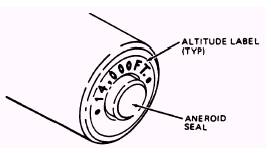
Figure 2-7.-Inspecting aneroid seal.
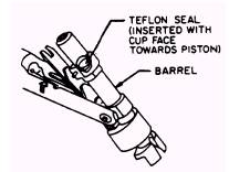
Figure 2-8.-Inspecting gasket seal. 9. Check the sealing compound on the aneroid screw, shown in figure 2-7. The seal must be intact and undisturbed. Cracks due to normal aging of seal material are acceptable. 10. Inspect the Teflon seal. Be sure that the cup side of the seal is facing the piston (fig. 2-8). |
 |