Custom Search
|
|
  |
|
|
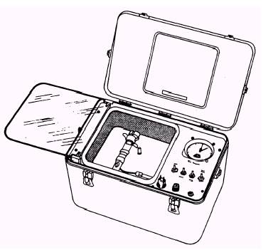
To check for the proper firing altitude of the automatic ripcord release, you must first be familiar with the automatic parachute ripcord release test set. AUTOMATIC PARACHUTE RIPCORD RELEASE TEST SET The automatic parachute ripcord release test set, shown in figure 2-9, is designed to test the sensitivity of the automatic ripcord release to a preset pressure altitude through use of an aneroid blocking mechanism. The principal action that you test is the consistency of the aneroid in actuating the release mechanism at a predetermined altitude. To do
Figure 2-9.-Automatic parachute ripcord release test set. 2-5 this, you first evacuate air from a test chamber to simulate an increase in altitude. When you have achieved a simulated altitude above the preset altitude of the ripcord release, you extract the arming pin, which arms the parachute ripcord release firing mechanism. Then you bleed outside air back into the test chamber at a controlled rate to simulate a specific rate of descent. When the pressure reaches the value for which the automatic ripcord release has been set, the aneroid will unlock the sear if the pressure sensitivity is within tolerance. The test chamber, its evacuation system, instrumentation, and controls are packaged in one container. The test chamber is designed to withstand a vacuum equivalent to an altitude of 30,000 feet. The chamber holds the entire 7000 series automatic parachute ripcord release, and it includes the necessary brackets to support and position the ripcord release within the chamber during the test cycle. An access door/observation window is also provided. NOTE: Before testing an automatic parachute ripcord release, the test chamber altimeter should read 29.92 inches of mercury barometric pressure. RIPCORD RELEASE TEST PROCEDURE Plug the test unit's power cord into a 115-volt, 60 Hz, ac power source. Place the power switch in the ON position, open the test chamber door, and insert the arming pin cable into the side of the ripcord release with the aneroid end toward the operator. To test the ripcord release, follow these procedures: 1. Ensure the test chamber has been calibrated. Install the test chamber substitute arming pin into the ripcord release. If the barometric pressure reading of the altimeter isn't 29.92, you will not get a true reading of the firing altitudes. Therefore, you must adjust the altimeter to the proper setting when required. 2. Install a dummy cartridge.
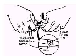
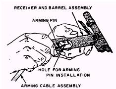
Figure 2-10.-Locking barrel assembly. CAUTION DO NOT RELEASE THE RIPCORD RELEASE FIRING MECHANISM WITHOUT A DUMMY CARTRIDGE INSTALLED, AS THIS COULD DIS-TORT THE FIREWALL. THIS DIS-TORTION COULD CAUSE A LATER MALFUNCTION. 3. Press the barrel down into position in the receiver. As the barrel reaches the proper position, exert forward pressure on the snap. lock, causing the snap lock pins to lock the barrel in position (fig. 2-10). 4. Install the barrel and receiver into the test chamber. Check your altimeter (fig. 2-9) for a setting of 29.92. 5. Evacuate the chamber to an altitude of 25,000 feet. This is done by using the climb toggle switch. 6. Decrease the altitude by using the descend toggle. The chamber simulates descent at a rate of 175 to 200 feet per second. 7. At approximately 20,000 feet actuate the arm toggle switch to withdraw the arming pin from the barrel and receiver. 8. At the firing altitude the ripcord release should fire. (You have a tolerance of plus or minus 1,000 feet at this time.) 9. Record the altitude at which the ripcord release assembly's firing pin strikes the dummy cartridge. The firing altitude is recorded on the parachute configuration, inspection, and history record. The quality assurance inspector will check this point of the procedure. WARNING AFTER TEST FIRING, YOU MUST NOT USE A METAL TOOL TO PUSH THE HAMMER AND LOCK AS-SEMBLY BACK FROM THE FIRING WALL. TAKE EXTREME CARE TO AVOID SCRATCHING OR ABRADING THE POLISHED SURFACE OF THE LOCK. THE PURPOSE OF THE LOCK ASSEMBLY IS TO MATE WITH THE ANEROID SEAR AND INITIATE FIR-ING AT A PRESCRIBED ALTITUDE. A ROUGH OR SCRATCHED LOCK-ING ASSEMBLY MAY CAUSE A HANGUP DURING THE UNLOCKING FUNCTION. NOTE: Ripcord release assemblies with part number 711-07022-30 (10,000-foot) must fire at 10,000 feet (plus or minus 1,000 feet) pressure altitude. Ripcord release assemblies with part number 711-07022-34 (14,000-foot) must fire at 14,000 feet (plus or minus 1,000 feet) pressure altitude. 10. Three firing altitude checks must be made. Any ripcord release that does not meet test requirements on all three checks will be rejected. Adjustments are not to be made. 11. Remove the dummy cartridge and inspect it for an indentation caused by the hammer firing pin striking the cartridge. This dent must be visible to the QA performing the inspection. ARMING AND ASSEMBLING THE AUTOMATIC PARACHUTE RIPCORD RELEASE The following instructions are the same type you will follow in the shop when arming and assembling the Model 7000 ripcord release. When you use the NAVAIR 13-1-6.2 manual and come to a step that is followed by "(QA)," that step must be inspected by a QA. 1. To arm the ripcord release that is installed in a parachute, your first step is to insert the arming cable housing through the holes in the parachute container and ripcord release pocket. 2. Next, feed the arming cable through the arming cable housing. Depending on application, the arming cable may be inserted at either side of receiver and barrel assembly (fig. 2-11).
Figure 2-11.-Installing an arming cable.
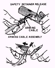
Figure 2-12.-Installing an arming cable housing. 3. With the ripcord release barrel in the open position, install the arming pin into the ripcord release. The pin must pass through the hole in the side of the receiver, through the firing mechanism lock, and out the opposite side of the receiver. 4. Next, you connect the arming cable housing to the receiver and barrel assembly. Ensure the safety retainer secures the housing to the receiver (fig. 2-12). Be sure that you check the cartridge service life at this time. You should not install a cartridge that will expire prior to the next scheduled repack of the assembly. Refer to NAVAIR 11-100-1 for the service/total life of cartridges. 5. You should enter the cartridge time delay, part number, type, expiration date, lot number, can open/installation date, the CAD DODIC (Department of Defense Identification Code), and the date of manufacture or overhaul on the parachute Configuration, Inspection, and History Record. 6. Insert a proper time-delay cartridge in the barrel. Refer to the applicable parachute chapter to determine which time-delay cartridge should be used. While you are pressing down on the barrel, look through the inspection hole in the receiver and ensure that the hammer assembly does not swing towards the firewall. If the hammer swings, the arming pin is improperly installed. Do not attempt to assemble the ripcord release any further, as this could fire the cartridge. 7. Press the barrel down into position in the receiver (fig. 2-10). As the barrel reaches proper position, exert forward pressure on the snap lock. This causes the snap lock pins to lock the barrel in position. Ensure that the snap lock is aligned with the alignment arrow. 8. Hold the ripcord release, as shown in figure 2-13, and slide the receiver and barrel assembly into the cover and power cable assembly until the holes for the screw are aligned. 9. Install the locking screw and lock washer. Apply a tamper dot to the locking screw, using red lacquer.
|
 |