Custom Search
|
|
  |
|
|
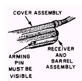
CHECKOUT OF ARMED RIPCORD RELEASE To check out an armed automatic ripcord release, you should proceed as follows: 1. Check the arming cable for proper installation, as shown in figure 2-14. The arming pin must be visible (extending through the side of the receiver).
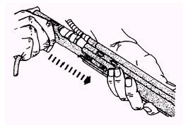
Figure 2-13.-Sliding receiver and barrel into cover assembly.
Figure 2-14.-Checking arming pin for proper installation.
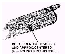
Figure 2-15.-Checking roll pin.
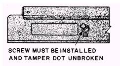
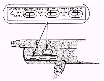
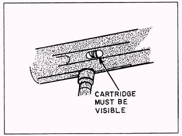
Figure 2-16.-Checking lock screw. 2. Check for correct position of the spring and centering of roll pin in hole (fig. 2-15). 3. Check to make sure the locking screw is installed. Be sure that the tamper dot isn't broken (fig. 2-16). 4. Check for proper position of the aneroid To install an automatic parachute ripcord (fig. 2-17) release, you must refer to the Emergency Personnel and Drogue Parachute Systems 5. The cartridge must be installed (fig. 2-18). Manual, NAVAIR 13-1-6.2. Look through the port and verify that the cartridge is installed. BALLISTIC SPREADING GUN ASSEMBLY 6. Complete the ripcord release installation in accordance with the applicable parachute chapter The ballistic spreading gun is a mechanically in NAVAIR 13-1-6.2. actuated device that ensures rapid inflation of the
Figure 2-17.-Checking for proper position of aneroid.
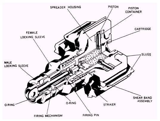
Figure 2-18.-Checking for cartridge. 2-9 main parachute canopy, and it reduces random inflation time of the canopy during high-speed ejections (figs. 2-19 and 2-20). DESCRIPTION The spreader gun assembly consists of a spreader housing, 14 pistons, slugs, and retainers, an impulse cartridge, a fail-safe mechanism, and a hardware retention lanyard. The spreader gun is provided with a fail-safe assembly in the event of a cartridge malfunction. The fail-safe assembly consists of a nylon sleeve clipped to the sheer band assembly. A safety pin is inserted in the firing mechanism during handling to prevent accidental firing. The cartridge for the spreader gun is threaded into the breech of the housing and has a retention cord attached. The spreader gun is positioned at the hem of the main parachute between the retaining cord and lower firing lanyards. The retaining cord is looped around the vent lines and the pilot parachute connector cord.
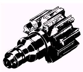
Figure 2-19.-Spreading gun assembly.
Figure 2-20.-Spreading gun assembly parts breakdown. 2-10 The lower firing lanyard is attached to the connector link next to the suspension lines. Two suspension lines and a loop from the parachute hem are attached to each slug. A cover plate holds the two lines and loop in the channels of each slug. OPERATION When actuated, the parachute canopy deploys by either an internal pilot chute or by the external pilot chute. Just prior to full canopy and suspension line deployment, the firing lanyard pulls the firing pin from the firing mechanism. This releases the striker, which strikes the cartridge primer. As the cartridge fires, the 14 slugs are propelled outward. They simultaneously drag the attached suspension lines outward in a 360-degree spread. This firing sequence occurs prior to any tension being placed on the suspension lines. Spreading is stopped when tension starts to build up in the suspension lines; so, at high speed it produces a 4-foot diameter mouth, and at low speed, it produces an 8-foot diameter mouth. In the event of a cartridge malfunction, a "fail-safe" backup subsystem operates. After the firing pin is withdrawn, the firing lanyard exerts 25 to 38 pounds of tension on the fail-safe assembly sleeve, which retracts the shear band assembly. This releases the slugs and allows the canopy to inflate aerodynamically.
|
 |