Custom Search
|
|
  |
|
|
REMOVAL OF BALLISTIC SPREADING GUN Before you work on a spreader gun, always ensure that a safety pin is installed. If you have to remove a damaged or defective spreading gun, proceed as follows: 1. Loosen the screws holding the plates to the spreading gun slugs to allow suspension lines to be removed. 2. Slip all the suspension lines and attached loops from under the plates. 3. Disconnect the retaining cord from the vent lines. 4. Tie one end of a temporary 20-foot line to the vent lines, and tie its other end to the free end of the retaining cord. 5. Pull the retaining cord out of the canopy from the skirt end. 6. Untie the temporary 20-foot line from the retaining cord, and remove the damaged or defective gun from the table. 7. To install a new or repaired spreading gun, follow the procedures outlined in the applicable parachute assembly chapter in the Emergency Personnel and Drogue Parachute Systems Manual, NAVAIR 13-1-6.2. BALLISTIC SPREADING GUN CARTRIDGE REPLACEMENT AND PULL-FORCE CHECK WARNING BEFORE YOU ATTEMPT TO RE-PLACE A CARTRIDGE, YOU MUST REMEMBER THE SPREADING GUN EMPLOYS AN EXPLOSIVE CAR-TRIDGE. FAILURE TO OBSERVE PROPER PROCEDURES COULD RE-SULT IN SERIOUS INJURY OR DEATH. NOTE: You must use only the special tools furnished for cartridge removal or replacement. It is recommended that a helper assist you in performing the cartridge replacement by verifying procedures as each step is accomplished. You must perform a firing pin pull-force check each time you replace a cartridge.
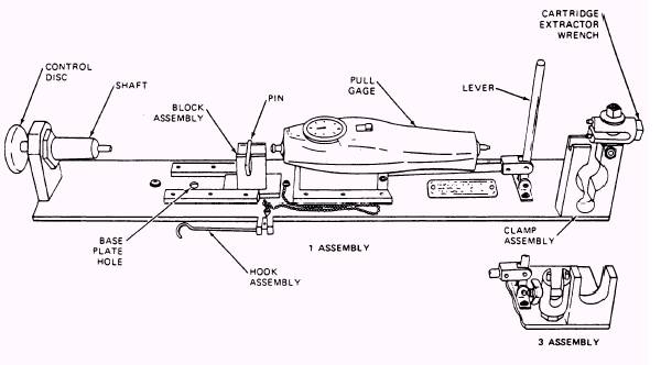
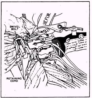
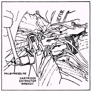
Figure 2-21.-Spreading gun test fixture. 2-12 By following the steps outlined below, you can replace the cartridge and perform the firing pin pull-force test in a safe manner. 1. Clamp the spreading gun test fixture to the packing table. Use one C-clamp positioned as close as possible to the clamp assembly. See figure 2-21 for the test fixture parts identification. 2. You must remove the cartridge extractor wrench from the swivel bolt attached to the spreading gun clamp assembly. 3. Then place the cartridge end of the spreading gun into a spreading gun clamp assembly (fig. 2-22). Ensure that the lip on the clamp assembly circles the spreading gun housing. Route the retaining cord through the vertical slot in the center of the clamp and spread suspension lines to prevent entrapment between gun and clamp. Position the swivel bolt in the horizontal slot in the clamp, and torque the swivel bolt nut to 7 1/2 foot-pounds. 4. Place the pins of the cartridge extractor wrench into holes in the cartridge. Loosen the cartridge using pressure against a 3/4-inch socket, as shown in figure 2-23. NOTE: If you have difficulty in removing the cartridge by using the extractor wrench furnished with the test fixture, use a special cartridge extractor tool. Cut and remove the retaining cord at the base of the cartridge. Place the slot of the special tool over the retaining cord pin, and loosen the cartridge by using a 1/2-inch socket. 5. Remove the spreading gun from the clamp or V-block assembly. Manually unscrew and remove the cartridge from the chamber. 6. Remove the cartridge from the retaining cord by removing the pin. Retain the pin for reinstallation if required. The old cartridge must be disposed of in accordance with current directives. 7. Remove the safety pin from the spreading gun. 8. Spread the canopy skirt hem and suspension lines to expose the cartridge chamber. Slide the spreading gun onto the test fixture shaft
Figure 2-22.-Placing spreader gun in gun clamp.
Figure 2-23.-Loosening cartridge. 10. Attach the hook assembly to the firing pin hole, and slide the hook assembly block over the nut that is attached to the pull gage. (See figure 2-21). 11. Move the switch on the pull gage to the center position. You must zero your meter needle by rotating the bezel on the dial. Move the switch to the full down position, away from the meter, for recording the pull force. 12. The QA verifies the test fixture lever firing pin releases. The pull force must go between 25 and 38 pounds. If a gun has failed the first test, it must be retested two more times. The gun must pass both retests. Record the force required to release the firing pin on the Parachute Configuration, Inspection, and History Record. When a gun fails, it is removed and returned to
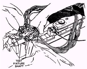
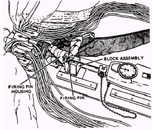
Figure 22-24.-Sliding on to test fixture. so that the shaft butts against the bottom of the cartridge chamber (fig. 2-24). 9. Open the four snap fasteners on the spreading gun extractor sleeve to expose the firing pin housing. Slide the block assembly at the center of the test fixture under the firing pin housing until the block assembly pin slides into the baseplate hole. Align the firing pin so that the hole in the firing pin is horizontal. The firing lanyard is located at the top. (See figure 2-25.)
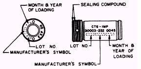
Figure 2-25.-Spreading gun installation. 10. Attach the hook assembly to the firing pin hole, and slide the hook assembly block over the nut that is attached to the pull gage. (See figure 2-21). 11. Move the switch on the pull gage to the center position. You must zero your meter needle by rotating the bezel on the dial. Move the switch to the full down position, away from the meter, for recording the pull force. 12. The QA verifies the test fixture lever firing pin releases. The pull force must go between 25 and 38 pounds. If a gun has failed the first test, it must be retested two more times. The gun must pass both retests. Record the force required to release the firing pin on the Parachute Configuration, Inspection, and History Record. When a gun fails, it is removed and returned to supply as a defective item. 13. After the pull-force measurement has been obtained, remove the hook assembly from the firing gun. 14. Push the firing pin back into the housing. Push the control disc firmly inward, forcing the firing pin out of the housing. Apply inward hand pressure to the firing pin as it moves out. Continue to move the control disc inward, applying hand pressure to the firing pin until it clicks into place. When a click is heard, the gun is cocked. Gently release the control disc while still exerting pressure on the pin. 15. The QA inspector must tug gently on the firing pin until the effect of spring loading is felt. If the pin moves without spring tension, the gun is not cocked, and step 14 must be repeated. 16. Release the block assembly by pulling the pin out of the hole in the baseplate and sliding the block away from the spreading gun. Remove the gun from the shaft. Do not remove the gun by pulling on the firing lanyard. 17. At this time, install the safety pin. CAUTION WHEN YOU ARE USING ALCOHOL TO CLEAN THE CARTRIDGE CHAMBER, DO NOT ALLOW ALCOHOL TO FLOW INSIDE THE GUN BECAUSE THIS COULD DAMAGE THE O-RINGS AND LUBRICATION. 18. Clean the cartridge chamber and threads with a small amount of denatured alcohol. Ensure that the old sealing compound and all foreign matter is removed. Tilt the gun to allow the alcohol to run out of the gun. 19. Feel the inside of the cartridge chamber to ensure that the slug pistons do not stick out inside the chamber. If the pistons do protrude, push them back as necessary. Feel the bottom of the chamber to ensure there is no foreign object in the chamber. The bottom should be smooth metal. 20. Prior to the cartridge installation, stamp on the cartridge, in the approximate position shown in figure 2-26, the following information: lot number, manufacturer's symbol, month and year of loading. Use black marking ink and make the characters as large as practicable for the available space. The same markings, plus expiration date and the can open date, must also be stamped on the cartridge head, using characters no smaller than 1/16 inch high. 21. Record the type of cartridge, part number, delay time, lot number, and service life expiration date on the Parachute Configuration, Inspection, and History Record. 22. Apply sealing compound to the top two threads of the cartridge. (See figure 2-26.)
Figure 2-26.-Cartridge markings-head and side. 23. Attach the new cartridge to the retaining cord by passing the pin through the screw base of the cartridge and the loop that is located at the end of the retaining cord. NOTE: Never force the cartridge into the chamber. This could damage the gun. When a cartridge is properly installed, the base should be approximately even with the top edge of the chamber. If the cartridge base is more than one thread above the edge, remove the cartridge and check the bottom of the chamber for any obstruction, such as protruding slug pistons. 24. Having inserted the cartridge into the chamber, you tighten it manually. If the cartridge stops before the threads are engaged, remove the cartridge and again check for protruding slug pistons. Push them back if necessary. 25. Replace the gun in the clamp or V-block assembly in accordance with steps 3 and 4. Using a cartridge extractor wrench and torque wrench with a 3/4-inch socket, you must torque the cartridge to 84 inch-pounds (plus or minus 12 inch-pounds). 26. Remove the spreading gun from the clamp or V-block assembly. Do not remove the safety pin. Put the cartridge extractor wrench back on the swivel/stanchion bolt. 27. Check stowage of the firing lanyard. Restow it if necessary. 28. Close the extractor sleeve. Now your job has been completed. To install a ballistic spreader gun onto a parachute, you must refer to the Emergency Personnel and Drogue Parachute Systems Manual, NAVAIR 13-1-6.2. Repacking a parachute with a ballistic spreader gun is discussed in chapter 3 of this manual.
|
 |