Custom Search
|
|
  |
|
|
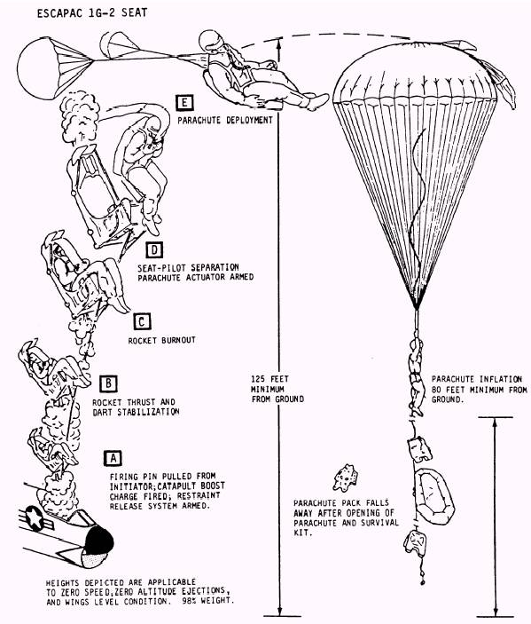
CHAPTER 3 NES-12 PERSONNEL PARACHUTE SYSTEM Learning Objective: Upon completion of this chapter, you will be able to understand the theory of operation and perform a speciaL inspection on the NES-12 parachute assembly. The modern high-performance aircraft used by the Navy today make extreme demands of emergency escape devices. The most critical time for ejection from an aircraft is at low altitudes- especially on takeoffs and landings. The ultimate goal in seat performance (to which engineers have been working) is one that safely ejects the occupant at zero airspeed and at zero altitude, at low altitudes under a high speed, or under other adverse altitude conditions. The system discussed in this chapter gives the aircrewman a zero airspeed and a zero altitude ejection system. The 1G series ejection seats separate from the aircrewman by means of a rocket that forcibly propels the seat away from the crew member after ejection. After the aircrew member ejects from the aircraft, a static line on the outside of the container pulls the external pilot chute from its pocket. The sequence of events shown in figure 3-1 commences. This static line is also attached to the arming cable for the automatic parachute ripcord release. The external pilot chute is intended to cause the parachute to open more rapidly, especially at low altitudes or during ground-level ejection. It is of a tristage design and functions as follows: At speeds from 0 to 90 knots, it will inflate to full diameter; at speeds between 90 to 250 knots, the full diameter will reduce to 24 inches; and at speeds in excess of 250 knots, it will invert, but its effective drag will be sufficient to stabilize the aircrew member during free fall and also aid in the extraction of the main canopy during deployment. At a preset altitude, the automatic ripcord release fires, pulling the ripcord pins from the locking cones, allowing the spring opening bands to open the container. The internal pilot parachute springs from the container and fills with air during this operation. The external pilot chute release assembly frees the shear link cable when the container opens. The internal pilot parachute causes the main canopy to be pulled from the container, followed by the suspension lines. A short piece of 18-pound nylon tape is used to momentarily shorten the canopy's effective length during low-speed ejection, which, in turn, promotes more positive opening characteristics. Just prior to full suspension line stretch, the ballistic spreading un fires, forcing the suspension lines out at the skirt hem. This rapidly opens the canopy and allows it to fill with air faster. Ties on the connector links break as load is applied, allowing the risers to be pulled from the container. NOTE: If the spreading gun fails to fire, the slugs separate from the gun assembly at full suspension line stretch, allowing the canopy to open aerodynamically. The aircrew member hangs suspended in his harness from the quick-release shoulder fittings during descent. The parachute has the four-line release system that was described previously. By manually actuating this system, the aircrewman is able to maneuver the parachute to a less hazardous landing site and to reduce oscillation during descent. Upon landing, the canopy and suspension lines can be disengaged from the integrated torso suit by means of the quick-release shoulder fittings. NOTE: After the incorporation of Aircrew System Change 446, the seawater activated release system provides an automatic backup method of releasing the risers after the crew member makes a seawater entry.
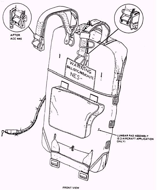
Figure 3-1.-Ejection system sequence of events. If the aircrew member should have to manually separate from the seat and initiate the parachute operation, only the internal pilot parachute will deploy the main canopy. The external pilot chute bridle is disconnected by means of the external pilot parachute override disconnect assembly, which is discussed later in this chapter. The NES-12 personnel parachute (fig. 3-2) is a back-type parachute used with an integrated
Figure 3-2.-Personnel Parachute Assembly, NES-12. 3-3 torso harness suit as part of an ejection seat escape system. The NES-12 parachute assemblies include a modified 28-foot diameter, flat nylon canopy with 28 gores. A ballistic spreading gun is used to rapidly deploy the canopy. The canopy is packed in a semirigid contoured container. These assemblies also include the tristage external pilot chute (EPC) and an internal pilot chute. The riser assembly, which includes the shoulder restraint system, is rigged to the container and is connected to the torso harness suit with quick-release fittings. The integrated torso harness suit combines the aircrewman's parachute harness and lap and shoulder restraint straps. The harness is channeled through the torso suit to retain it in position and to aid in donning. When aboard the aircraft and seated, the aircrewman connects the quick-release fittings on the parachute riser assembly to the quick-release fittings on the parachute integrated torso suit. The survival kit and the lap restraint system are also connected to the integrated torso suit by means of quick-release fittings.
|
 |