Custom Search
|
|
  |
|
|
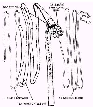
RIGGING To obtain the NES-12 parachute, you order each component separately. You must rig the parts together to forma complete assembly. When you start to work on this or any parachute, the rigging and packing will be done under ideal conditions in a parachute loft. When a parachute assembly must be packed under unfavorable conditions, provisions must be made to protect it from possible damage and excessive humidity. Quality assurance (QA) points are included in rigging and packing procedures. When a step is followed by "(QA)," it is a QA requirement. All work STOPS until a quality assurance inspector performs the requirements listed at the end of the applicable procedure. The packing of a parachute assembly must NOT be interrupted after the packing operation has been started. If unforeseen circumstances cause the packing operation to be interrupted, the parachute assembly must be completely repacked. The rigging covered in this chapter applies to an original issue parachute assembly. NOTE: This rate training manual is not to be used as a substitute for the NAVAIR 13-1-6.2 or the NAVAIR 13-600-4-6-3 manuals. After you have laid out the parachute and connected the connector links to the proper tension hooks, attach the internal pilot parachute. This is done by routing the small loop of the bridle assembly through the loop in the pilot parachute. Pass the free end (large loop) of the bridle assembly through the small loop, forming a lark's head knot. Draw it tight. Pass one free end (large loop) of the bridle assembly around the canopy vent lines at the peak of the canopy. Pass the pilot parachute through the large loop of the bridle assembly, forming a lark's head knot, and draw tight. Now, attach a tension strap to the canopy vent lines and tighten it. At this time, you should inspect the complete parachute assembly following the directions in NAVAIR 13-1-6.2 and NAVAIR 13-600-4-6-3. This inspection has been covered in chapter 1 of this manual. INSTALLATION OF SPREADING GUN A ballistic spreading gun (fig. 3-3) is used in the parachute. The procedures for inspecting this device was discussed in chapter 2. After the parachute has been inspected and
Figure 3-3.-Ballistic spreading gun assembly.
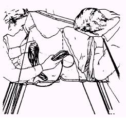
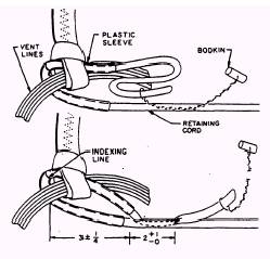
Figure 3-4.-Routing line for pulling retaining cord through canopy. rigged, install the spreading gun using the following procedures: WARNING BEFORE COMMENCING ANY FUR-THER OPERATIONS, ENSURE THAT THE SAFETY-PIN IS INSTALLED IN THE SPREADING GUN. Tie apiece of Type III nylon suspension line 20 feet long to a shot bag (fig. 3-4). Throw the shot bag attached to the line through the canopy gores so that it reaches the canopy peak. Then pull the shot bag through the vent hem and tie the line temporarily to the vent lines. Secure the bottom end of this line to keep it in place while you whip and fold the canopy. When the canopy has been whipped and folded, tie the free end of this line to the end of the spreading gun retaining cord and pull the retaining cord through the canopy and out the peak. Untie the Type III nylon line from the retaining cord and vent lines, and route the retaining cord through the lark's head knot in the pilot parachute connector strap and under all the vent lines. The retaining cord has a plastic sleeve that should be centered over the indexing line on the retaining cord. Align the indexing line on the retaining cord above the vent lines. With the help of a bodkin tool, telescope 2 inches of the retaining cord into itself to form a
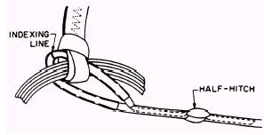
Figure 3-5.-Rigging retaining cord. 3-inch loop ( 1/4 inch) around the vent lines and connector strap, as shown in figure 3-5. Cut 1 inch off the end of the retaining cord at a 45-degree angle. Tie a half-hitch around the retaining cord and complete the splice by telescoping the remainder of the end into the retaining cord, as shown in figure 3-6. Work the line until it becomes smooth on the inside of its casing. Tack the end inside the retaining cord with two turns of waxed nylon 6-cord, doubled. Tie the ends with a surgeon's knot followed by a square knot. Now position the spreading gun at the skirt hem. Place the spreading gun between the suspension line groups 1 through 14 and 15 through 28 so the retaining cord of the gun faces the canopy. Remove the tension strap from the canopy peak.
Figure 3-6.-Rigging retaining cord (completed splice).
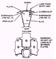
Figure 3-7.-Attachment of spreading gun to suspension lines. Rotate the gun so the slug labeled "14-13" is facing up, and loosen the screws and plate on this slug. You will find two slots on the face of each slug. One is "closed" or covered when the plate is in place. The other is open to the side of the slug (fig. 3-7). Place suspension line number 13 and one side of the loop of line attached to the canopy hem in the closed slot of the slug (fig. 3-8). Place suspension line 14 in the open slot of the same slug. Pass the loop around the plate and over the suspension line in the slug. Secure the plate to the slug with screws and ensure the suspension lines move freely in the slots. Torque the plate screws to 6 (plus or minus 1/2) pound-inches and apply red tamper dot. Secure the remainder of the suspension lines and loops to corresponding slugs in the same manner. Work from suspension line 12 through 1 and from line 15 through 28 (fig. 3-9). After the above procedures are completed, you must have a QA inspect the completed installation of the spreading gun.
|
 |