Custom Search
|
|
  |
|
|
THE EXTERNAL PILOT PARACHUTE A special feature of the NES-12 parachute is the external pilot parachute. To function properly,
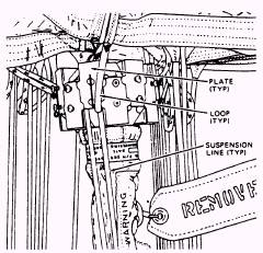
Figure 3-8.-Installing suspension lines.
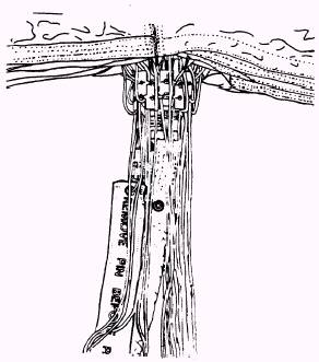
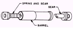
Figure 3-9.-Complete set of suspension lines. the external parachute is connected to the cord that links the internal pilot chute to the main canopy vent lines. A special device is used to jettison the external chute at high speeds. This device is the override disconnect assembly, shown
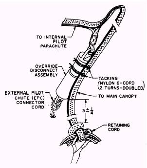
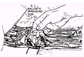
Figure 3-10.-Override disconnect. in figure 3-10. It consists of two hooks or sears that are kept in engagement as long as they are inside the barrel. As long as tension is applied to the external pilot chute connection, the override will remain locked. Once the internal pilot chute takes control of the tension, the override connection will release or unlock, allowing the external pilot chute to be released. To attach the external pilot parachute, proceed as follows: 1. Insert the spring and sear (fig. 3-10) into the wide end of the barrel assembly of the override disconnect. The spring and sear will be connected to the external pilot chute bridle, as shown in figure 3-11. With the aid of a temporary locking pin, push the sear into the barrel until it is protruding from the other end. 2. Engage the sear attached to the internal pilot chute connector cord with the sear, which is protruding from the override disconnect, and release the tension by removing the temporary locking pin. This will cause the two sears to lock within the barrel assembly of the override disconnect. As you can see in figure 3-11, the external and internal pilot chutes are now locked together. 3. Tack the override disconnect to the internal pilot parachute connector strap 3 inches (plus or minus 1/4 inch) above the knot, securing the connector strap to the vent lines at two places. Use two turns of waxed nylon 6-cord (V-T0295), doubled, for each tacking. Tie the ends with a surgeon's knot followed by a square knot. SUSPENSION LINE CONTINUITY CHECK WITH SPREADING GUN INSTALLED Although you have checked the continuity of suspension lines prior to installing the spreader gun, they must be checked again to ensure that you haven't gotten any lines out of sequence or have crossed a line causing a twist. To check suspension lines continuity, proceed as follows: WARNING ENSURE THE SAFETY PIN IS IN-STALLED IN THE SPREADING GUN (FIG. 3-12).
Figure 3-11.-Tacking override disconnects.
Figure 3-12.-Inserting safety pins. . If the canopy isn't already under tension, attach a tension strap hook to the canopy vent lines and tighten.
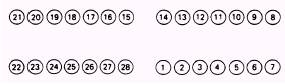
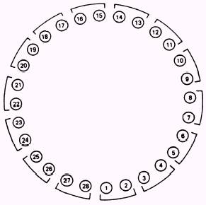
Figure 3-13.-Arrangement of suspension lines on connectorlinks. . The suspension line must be arranged on the connector links, as shown in figure 3-13, and on the spreader gun, as shown in figure 3-14. The spreader guns must be turned so that suspension lines 15 and 14 face up. The suspension lines must pass through corresponding numbered slots in the spreading gun slugs. Ensure that the loops attached to the odd numbered suspension lines pass through the slots in the odd number of slugs. . Suspension lines must run free from the skirt hem, through the corresponding numbered slot in the spreading gun slugs, and to the connector links without any dips or twists. STRAIGHTENING CANOPY GORES WITH SPREADER GUN INSTALLED It would be impossible for you to whip and fold a canopy with a spreading gun installed. For this reason you will have to straighten the gores instead of whipping and folding. Always ensure the safety pin is installed in the spreading gun and the spreading gun firing lanyard is detached from the connector link. 1. The helper should place a shot bag on the helper's side of the skirt hem. 2. The packer rotates all gores on the packer's
Figure 3-14.-Arrangement of suspension lines on spreading goesgun. side as a group, except the bottom gore; it over to the helper's side of the packing table. The packer straightens and smooths the bottom gore on the packer's side of the table throughout its length to the peak. 3. The packer returns each gore above the shot bag on the helper's side of the packing table to the packer's side, one at a time. Each fold is straightened and smoothed, as shown in figure 3-15. 4. The folded gores on the helper's side should be straightened and smoothed in the same manner.
|
 |