Custom Search
|
|
  |
|
|
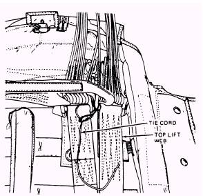
ATTACHMENT OF CONTAINER ASSEMBLY TO RISER ASSEMBLY To attach the container assembly to the riser assembly, you must remove the tension strap from the canopy peak, and remove the tension hooks from the connector links and the packing table. Rotate the risers onto the container, and secure the riser retainer fittings to the riser retainer supports (fig. 3-26). Now, position the lift web protector flaps over the riser and install the break cords. These two break cords, approximately 2 inches apart, are constructed with one turn of waxed size FF nylon thread, doubled. Pass the threads through the protector flap, under a support, up through the protector flap, and tie them snugly with a surgeon's knot followed by a square knot, as shown in figure 3-27. Repeat this procedure for the other riser. INSTALLATION OF CONNECTOR LINK TIES The connector link ties are a very important part of the rigging of the NES-12 and other parachutes that use the ballistic spreading gun. Not only do they prevent the risers from moving around inside of the container, they also prevent the premature deployment of the risers (riser blowout), which could cause line entanglement or premature firing of the spreader gun and provide an anchor point for the firing of the spreader gun.
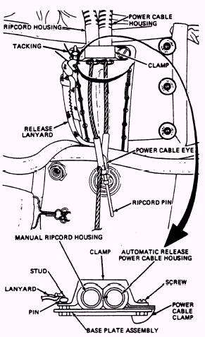
Figure 3-29.-Tying connector links. Now position the connector links side by side so that the top connector links are to the right of the bottom connector links, then form a noose around the connector links located on the helper's side with one of the 100-pound tie cords, as illustrated in figure 3-29. Tighten the noose and tie the free end of the tie cord to the bottom inboard cloth retaining band loop with three to four half-hitches. Trim excess cord. Using the other tie cord in the same manner, secure the connector links on the packer's side. INSTALLATION OF RELEASE ASSEMBLY LANYARD AND RIPCORD ASSEMBLY Proceed in installing the lanyard release and ripcord assemblies by marking the clamp release lanyard 36 inches from the locking pin end. Next, fold the top end flap onto the container so that the baseplate faces up. WARNING ENSURE THAT THE BASEPLATE CLAMP IS POSITIONED OVER THE HEX NUT PRIOR TO INSTALLING THE LOCKING PIN (FIG. 3-30).
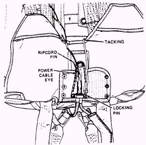
Figure 3-30.-Release lanyard assembly. Now, position the clamp over the end fitting of the power cable housing. Insert the baseplate screw through the clamp holes and into the righthand baseplate hole so that the clamp flange fits over the end of the baseplate, shown in figure 3-30. Position the large slotted end of the baseplate clamp under the screwhead on the baseplate. Position the manual ripcord housing and power cable housing under the clamp with two flat sides together and the other two flat sides positioned against the baseplate. Place the clamp in the clamping grooves of the two housings. Position the small slotted end of the baseplate clamp over the baseplate stud. Insert the release lanyard locking pin into the stud hole. Secure the clamp in place. The locking pin should be finger tight; if necessary, slightly loosen the screw. Ensure the two housings are correctly positioned and securely retained. Safety-tie the locking pin to the stud with one turn of waxed size FF nylon thread (V-T-295), single. Pass the thread through the lanyard knot and tie the ends with a surgeon's knot, followed by a square knot. The next procedure is to insert the top ripcord pin through the beveled side of the eye in the power cable. Route the lanyard over the helper's side of the top end flap V. Tack the lanyard to the top end flap at the V with 1/8-inch slack between the locking pin and the tacking, passing the tacking around the lanyard. Use one turn of waxed size E nylon thread, single. Tie its ends with a surgeon's knot, followed by a square knot (fig. 3-31). Route the lanyard along the inside of the top end flap to the helper's side of the automatic actuator power cable buttonhole. Tack the lanyard to the upper edge of the container with one turn of single, waxed, size E nylon thread (fig. 3-32), allowing 1/8 inch of slack between the tackings. The tacking must pass around the lanyard and not through it. Tie the ends with a surgeon's knot, followed by a square knot.
Figure 3-31.-Tacking locking pin.
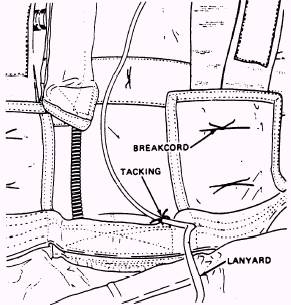
Figure 3-32.-Tacking release lanyard. Reeve the lanyard through the lanyard guide grommet (fig. 3-33). Place the 3`6-inch mark on the lanyard over the bar on the inboard connector link located on the helper's side. Secure the lanyard to the connector link bar with a bowline knot. Ensure the lanyard is positioned between the webbing and the connector link end. Tie an overhand backup knot in the end of the lanyard. You should have the QA inspect your work at this point.
|
 |