Custom Search
|
|
  |
|
|
INSTALLATION OF AUTOMATIC PARACHUTE RIPCORD RELEASE ASSEMBLY You have read about the automatic parachute ripcord release in chapter 2 of this manual. At this time, you will see how it is installed into a container. Before you actually attempt to install a release assembly, (fig. 3-23), you must first make sure that the inspection requirements in the NAVAIR 13-1-6.2 and the NAVAIR 13-600-4-6-3 have been complied with. Now you are ready to proceed with the installation. First, rotate the risers over the suspension lines and position the container on the packing table so that the bottom end is towards the canopy and the inside faces up. Attach and crimp one end of both short container spring opening bands to the container eyes with hooks facing down (fig. 3-24).
Figure 3-22.-Engaging snaps. You will find that different parachutes use different lengths of arming cables. There are also several different time-delay cartridges that can be used at this time. Before you attempt to install the arming cable or the cartridge, check the NAVAIR 13-1-6.2 to ensure you are using the right ones. Inspect, arm, and assemble the automatic parachute ripcord release in accordance with the NAVAIR 13-1-6.2. Record the time delay, lot number, DODIC, part number, type of cartridge, and the expiration date on the Parachute Configuration, Inspection, and History Card. Now you are ready to install the ripcord release into the ripcord release pocket, close the slide fastener, and secure the protector flap. Insert the power cable through the buttonhole in the top end of the container. Route the end of the arming cable housing through the housing port located in the right side of the release pocket and through the buttonhole located on the right side of the container (fig. 3-25). Close the fastener flaps of the release pocket.
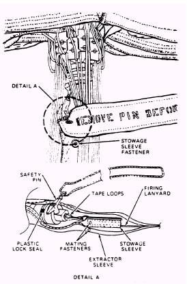
Figure 3-23.-Automatic parachute ripcord release assembly.
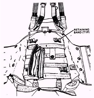
Figure 3-24.-Installing retaining bands.
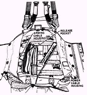
Figure 3-25.-Inserting power cable.
Figure 3-26.-Rotate risers.
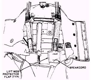
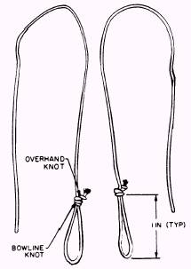
Figure 3-27.-Installing break cords. To install connector link ties, proceed as follows Cut two 12-inch lengths of 100-pound nylon cord and sear the ends. (Do not use waxed cord). Then, form a 1-inch loop in one end of each of the cords and secure with a bowline knot. Tie an overhand backup knot in the end of the cord (fig. 3-28).
Figure 3-28.-Connector link ties.
|
 |