Custom Search
|
|
  |
|
|
CANOPY INSPECTION Inspecting the canopy requires the most time. You must take your time in order to be certain that you don't miss any defects. NAVAIR 13-600-4-6-3 and NAVAIR 13-1-6.2 spell out the step-by-step procedures for this inspection. Any damage must be recorded on a canopy damage chart. (See figure 1-15.) To inspect the canopy for possible defects or damage, you should take the following steps: 1. Lay the canopy on a clean packing table so its nameplate gore is facing down. 2. Place tension on the canopy. 3. Have your helper raise the suspension line. Use Y-stands at the skirt hem to hold the suspension lines. 4. You, as the packer, start at the skirt hem and inspect the upper radial seam from skirt hem to peak. You inspect the vent hem, collar and ring, lower radial seam, fabric surface, diagonal seams or tapes, and skirt hem. Minor defects that do not weaken the assembly are not reported on a canopy damage chart. If necessary, minor defects may be corrected by light brushing or trimming. 5. Significant damage and major defects, such as holes, rips, tears, or contaminated areas that have to be removed, are reported on the canopy damage chart. Use the same procedures to inspect all canopy gores. SUSPENSION AND VENT LINE INSPECTION To inspect the suspension lines, you and your helper grasp one group of suspension lines at the connector links and walk toward the canopy skirt hem, allowing the lines to run freely over the palm of your hand. Visually examine the lines for damage and defects. Upon reaching the skirt hem, grasp the remaining groups of lines and inspect them the same way, walking toward the connector links. The lines at the canopy vent are also visually examined. Your inspection includes, but is not limited to, the following: 1. General condition of the suspension lines including fraying, ruptures, inner cores protruding from lines; dirty, lumpy, hard or thin spots; friction bums; improper overlap length; presence
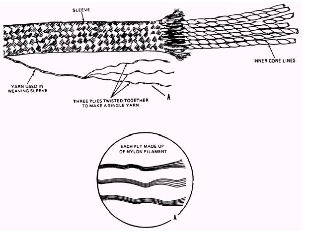
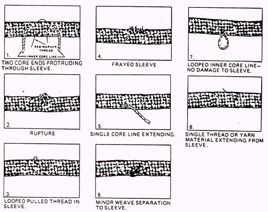
Figure 1-16.-Suspension line construction. 1-26
Figure 1-17.-Suspension line damage. of twists in individual lines; and the proper sequence of lines on the connector links. To help you decide on the various types of damage, see the examples in figures 1-16 and 1-17. 2. Be sure that each of the suspension lines is in proper rotation at the connector links and through the canopy. 3. On an original issue inspection, you must measure the suspension lines for proper length. Apply a 20-pound tension to each line. The length of the shortest line and the length of the longest line must not vary more than 2 inches. 4. Inspect the attachment at the skirt hem for thin spots at the V-tabs; also, check the condition of the V-tabs. 5. Inspect the four line release system. The four line release system permits four of the suspension lines on one side of the parachute to be detached from the connector links during a parachute descent. This permits the parachutist to dampen oscillations and to have some control over the direction the parachute travels when descending. 6. Other defects should be noted on the Parachute Configuration, Inspection and History Card. If a defective line is found that would affect the safe operation of the assembly, the line must be replaced at a depot-level maintenance activity. |
 |