Custom Search
|
|
  |
|
|
Seat Removal and Installation
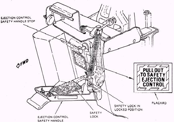
Before entering the cockpit, ensure that all seat and canopy safety pins and devices are properly installed. Check that the ejection control safety handle (fig. 6-13)
(head knocker) is in the down and locked position. Ensure that the pilot's and copilot's eject mode selector handles are set to the SELF EJECT position. Remove the parachute and survival kit by disconnecting the oxygen and communications quick-disconnect. Disconnect the emergency oxygen and emergency radio beacon quick-release lanyard attached to the aircraft's structure. Squeeze the harness release handle and disengage from holder. Remove the parachute actuator arming cable from the handle, and pull upward
on the handle until the harness release actuator locks in the MANUAL DETENT position. Reseat the handle into the holder. Withdraw the inertia reel straps from the chute roller fittings. Rotate the aft end of the survival kit up and forward to release the forward mounting hooks from the seat mounting brackets. Remove the parachute and survival kit from the aircraft and deliver to the aviators equipment work center. If the seat is not in the full down position, apply electrical power and lower the seat to the full down position. Do not hold the seat adjust switch in the UP or DOWN position for more than 15 seconds to prevent damage to the seat height actuator. Remove the M99 initiator actuating cover and install safety pins in the initiators (fig. 6-5). The pilot and copilot seats require two safety pins, and the TACCO and SENSO seats require one safety pin. Remove, as required, overhead window or hatch assembly. Remove cover from top of the
Figure 6-13.- Ejection control safety handle. rocket catapult (fig. 6-14). Disconnect the inertia reel ballistic hose quick disconnect using the special key and flag assembly. Attach the hoisting sling to the seat and overhead hoist. Using the hoist, apply upward pressure on the seat to prevent damage to the seat/ rocket during removal of the trunnion bolt. Remove the trunnion bolt and ensure that all seat connections have been disconnected. Raise the seat with the hoist. As the seat reaches the top of the guide rails, prevent the yaw vane from deploying. Caution must be taken to prevent injury to maintenance personnel as the yaw vane is deployed by a 40-pound spring force. Continue raising the seat until the lower rollers on the seat clear the guide rails. After the yaw vane trip lever has passed the cam on the outboard guide rail, reset the yaw vane latch. Lower the seat and secure it to the ejection seat cradle. CAUTION Do not rest the seat on the STAPAC cover on the bottom of the seat. The seat installation is essentiality a reversal of the removal procedures. NOTE: The following text provides informa-tion for in-shop maintenance of the ESCAPAC lE-1 ejection seat.
|
 |
|
|