Custom Search
|
|
  |
|
|
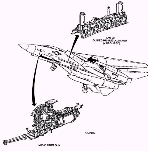
Multiple Weapons Release System The multiple weapons release system has basic controls and components and multiple weapons system controls and components. They are discussed in the following paragraphs. The bomb release and rocket control systems enable selecting, preparing, and delivering of the air-to-ground stores. Weapons that can be carried on stations 3R, 4R, 5R, and 6R range from general-purpose bombs of various sizes to CBU, and GBUs. M61A1 20-MM Automatic Gun Fire Control System The M61A1 20-mm automatic gun fire control system enables selecting, arming, and firing of the gun. Depending upon the mission objective, the gun fire control system can be operated in an air-to-ground (A/G), air-to-air (A/A), or air combat maneuver (ACM encounter) mode. Two attack modes of operation are available-computer pilot attack mode and manual attack mode. The computer pilot attack mode operates with the weapon control system, command signal decoder system (CSDC), and the vertical display indicator system to display target data. The manual attack mode is used primarily as a backup mode to provide a manually controlled sight reticle if a system malfunction occurs. GUN RATE SWITCH. The GUN RATE switch (fig. 15-1) is located on the ACM panel. It is a two-position, push-button, indicator switch that selects HIGH (6,000 rounds per minute) or LOW (4,000 rounds per minute) rate of fire. This switch is only active in the A/G and A/A modes. A/G GUN SWITCH. The A/G GUN switch (fig. 15-2) is located on the armament control indicator panel. It is a two-position toggle switch that enables or inhibits a mixed bomb and gun mode operation. The MIXED position enables bomb and gun mode operation while the OFF position inhibits it. GUN CONTROL UNIT. The gun control unit, located above the gun barrels, contains the BURST selector switch. This switch limits the number of rounds that can be fired per burst (50, 100, or 200), or it permits unrestricted firing (MAN position). HOOK/GUN PANEL. The HOOK/GUN panel, located on the forward cockpit vertical console, contains the gun rounds counter. This counter provides a digital countdown readout of the rounds remaining. The F-14 aircraft uses the AN/ALE-39 decoy dispensing system. The CHAFF/FLARE DISPENSE panel is located on the aft cockpit right side console. The MANUAL DISPENSE switch on the CHAFF/FLARE DISPENSE panel is used to initiate rounds from the aft cockpit. Rounds can also be initiated from the forward cockpit by the decoy dispense push button on the control stick. Jettison System The jettison system allows jettison of certain external stores. There are four jettison modes: 1. Emergency, which is pilot controlled 2. ACM encounter, which is NFO selected and pilot controlled 3. Selective, which is NFO controlled 4. Auxiliary, which is NFO controlled (BRU-32 air-ground weapons) In all modes, arming and fuzing is disabled during jettison operations. The landing gear handle must be UP for ACM encounter, selective, and auxiliary jettison modes. Aircraft Armament Configuration Capabilities The basic armament configuration (fig. 15-3) of the F-14 aircraft consists of four fuselage-mounted LAU-92
Figure 15-3.-Basic armament configuration. missile launchers and an internally mounted M61A1 For more information on the authorized 20-mm gun. However, the aircraft has a total of eight configurations of aircraft, you should refer to F-14 weapons stations that hold a variety of missile launchers Tactical Manual, NAVAIR 01-F14AAA-1T. If you and weapons rails. Figure 15-4 shows the location of weapons want more information on F-14 weapons systems, refer stations 1 through 8. Figures 15-5 through 15-11 show to Airborne Weapons/Stores Loading Manual, NAVAIR the various station and equipment configurations. 01-F14AAA-75.
Figure 15-4.-Location of weapons stations.
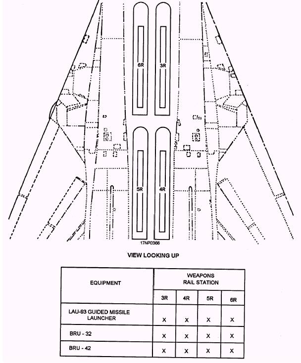
Figure 15-5.-Station configuration capabilities.
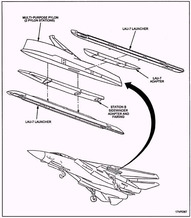
Figure 15-6-LAU-7 configuration on aircraft.
Figure 15-7.-LAU-92 configuration on aircraft.
Figure 15-8.-LAU-93 configuration on aircraft.
Figure 15-9.-Air intercept missiles configuration on aircraft.
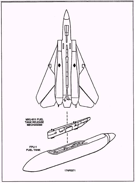
Figure 15-10.-Fuel tank configuration on aircraft.
Figure 15-11.-Decoy dispenser configuration on aircraft. |
 |
|
|