Custom Search
|
|
  |
|
|
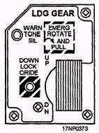
F/A-18 AIRCRAFT The F/A-18 aircraft is a single-seat, dual-role (fighter/bomber), supersonic aircraft. External electrical power can be applied at the external power receptacle on the left side of the forward fuselage. This is easily accessible from the deck level. The external power connector connects 115/208-volt, three-phase, 400-hertz ac external power to the ac bus. When external power is not available, the aircraft has an auxiliary power unit (APU) to drive either of the aircraft generators for functional checkout of the aircraft system. The systems and subsystems of the F/A-18 aircraft armament system are discussed in the following text. The aircraft armament system, basic controls, and components all function in relation to each other. Ground Power Control Panel Assembly The ground power control panel assembly has four toggle switches. Three of these switches control the application of external power to avionic and instrument systems. This prevents excessive equipment operating time because of other unassociated ground operations. The EXT PWR (external power) switch is a three-position switch used to apply electrical power to the aircraft. In the NORM (normal) position, electrical power is supplied to the aircraft. In the OFF position, no power is supplied to the aircraft. The RESET position resets power for the external monitoring circuit when there is a temporary overload. Switch 1 is a three-position switch with B ON to provide enabling power to the mission computers. Switch 2 is a three-position switch with B ON to provide enabling power to the digital display indicators (DDIs). The B ON switch also enables power to the aircraft radar. Switch 3 is a three-position switch with B ON to provide enabling power to the armament computer stores management panel (SMP), AN/AWW-4 system, HARM system, and the AN/ALE-39 system. In the DN position, the LDG GEAR control (fig. 15-12) disables normal weapon release, launch, and fire signals. In the UP position, 28-volt dc power is applied
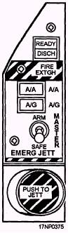
Figure 15-12.-Landing gear control handle. from the main landing gear weight-off-wheels relay to the master arm circuit breaker. Armament Safety Override Switch The armament safety override switch (fig. 15-13) is in the maintenance panel located in the nosewheel well. In the override position, it overrides the landing gear handle DN position so ground operational maintenance can be pulled on the weapon systems. Master Arm Control Panel Assembly The master arm control panel assembly (fig. 15-14) is located in the forward cockpit. It contains the A/A, A/G, and MASTER switches. The A/A and the A/G are push-button switches that provide a ground to the SMP. They select the air-to-air or air-to-ground computer modes, respectively. The MASTER switch is used with the LDG GEAR handle or the armament safety override switch. In the SAFE position, weapons cannot be released or fired, although emergency jettison can be initiated. The ARM position provides an input to the SMP and power for weapon release, fire, or jettison. The switch position (SAFE/ARM) is displayed on the DDIs in the wing-form display.
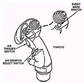
Figure 15-14.-Master arm control panel assembly. Aircraft Controller Grip Assembly The aircraft controller grip assembly (fig. 15-15) contains the A/G weapons release switch (bomb release switch). The switch is spring-loaded to the OFF position. When the switch is pressed, it completes a circuit from the armament computer and provides an input back to the armament computer. The aircraft grip controller assembly also contains an A/A switch and the trigger switch, which is discussed later in this chapter.
Figure 15-13.-Armament safety override switch.
Figure 15-15.-aircraft controller grip assembly.
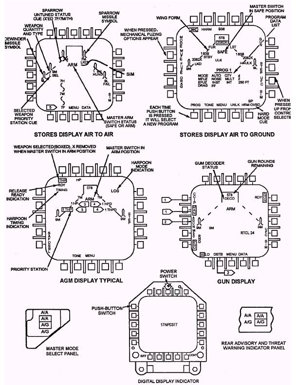
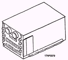
Figure 15-16.-Digita1 display indicators. 15-16 The digital display indicators (DDIs) (fig. 15-16) are located on the rear cockpit instrument panel vertical consoles. The DDIs on aircraft 161354 through 163778 are connected in parallel with the DDIs in the front cockpit and respond to the last action taken by either pilot. Rear DDIs on F/A-18D 163986 and up have independent displays. Armament Computer The armament computer (fig. 15-17) is interfaced with and controlled by the mission computers. The armament computer is also interfaced with and controls the weapon station command encoders-decoders. The armament computer has a weapon insertion panel (fig. 15-18) with code wheels. These code wheels are used to enter the code into the weapon-type (ARMAMENT') and nose or tail fuzes (FUZING). The weapon-type code must match the weapon loaded, and the nose fuze or tail fuze code must be compatible with the weapon or the armament computer won't allow it to release normally. For weapons without nose or tail fuzes, the codes must still match the weapon loaded Two digital computers makeup the mission computer system and control the avionics systems. They interface with the armament computer and allow the armament computer to route power to the encoders-decoders for weapon release. The digital computers are controlled by the MC switch on the MC/HYD ISOL panel. Jettison System The jettison system gives the pilot or crew a way to jettison weapons, stores, launchers, and fuel tanks. The
Figure 15-17.-Armament computer. jettison system has three modes of release-emergency jettison, selective jettison, and auxiliary jettison. The emergency jettison mode jettisons all weapons from the five pylon stations. The selective jettison mode individually jettisons the left fuselage missile, the right fuselage missile, racks, launchers, and stores. The auxiliary jettison mode is a gravity mode to jettison the five pylon stations when emergency and/or selective jettison fails. |
 |
|
|