Custom Search
|
|
  |
|
|
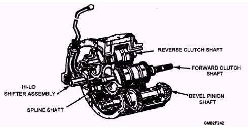
The mechanical drive train found in construction equipment is similar to that of the automatic transmission in that a transmission is used in conjunction with a torque converter and shifting is accomplished hydraulically when the operator moves the range selector lever. Power Shift Transmission NOTE
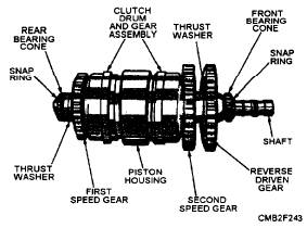
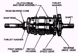
Figure 6-1.- Power shift transmission. The REVERSE CLUTCH SHAFT (fig. 6-2) has a straight roller bearing at each end, with the reverse driven gear keyed to the front of the shaft. The shaft consists of first and second speed drive gears riding on bushings and is welded to the dual hydraulic clutch pack assemblies. The FORWARD CLUTCH SHAFT (fig. 6-3) rotates on straight roller bearings at the rear and ball bearings at the front, with the reverse drive gear keyed to the front of the shaft. As with the reverse clutch shaft. the forward clutch shaft consists of first and second speed drive gears riding on bushings and is welded to the dual hydraulic clutch pack assemblies.
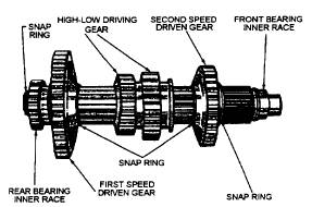
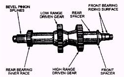
Figure 6-2.- Reverse clutch shaft. The SPLINE SHAFT (fig. 6-4) rotates on two straight roller bearings. The rear bearing is mounted in the transmission case; the front bearing is mounted in the transmission cover. The first and second driven gears are held in position on the spindle by snap rings and are constantly meshed with the first and second speed drive gears on the clutch shafts. The hi-lo driving gear slides freely on the shaft and drives the bevel pinion shaft when brought into mesh with either the high or low range driven gear by means of the hi-lo shifting lever. The BEVEL PINION SHAFT (fig. 6-5) consists of the high and low range gears, which are keyed to the shaft. The shaft is supported at the rear by a straight roller bearing, and, at the front, by a double-row taper roller bearing. The pinion gear is splined to the rear of the pinion shaft and is held in place by a nut. A shim pack is provided between the front bearing cage and the transmission case front cover for adjusting pinion depth.
Figure 6-4.- Spline shaft.
|
 |
|
|