Custom Search
|
|
  |
|
|
The heart of the clutch is contained in two pistons- the accelerator piston and the force piston. Pump oil volume is not needed to fill the applying clutch cavity, and only relatively low volume is needed to pressurize the clutch. In neutral, all accelerator and force piston cavities are filled with oil at lube pressure (10 to 25 psi). A selector valve, located on the top of the transmission case, directs the oil to the accelerator piston cavity and, in turn, to the force piston cavity. Once the pistons are filled with oil, they remain full under lube pressure. Other small cross-drilled passages furnish a constant supply of lube oil to the drive gear bushing, the drum assemblies, and the clutch hubs for distribution through the clutch plates. In neutral, neither clutch is engaged, the drive gear and drum assemblies are free. and no torque is transmitted through the clutch, as shown in figure 6-6. Upon application of the clutch, main oil pressure (approximately 200 to 300 psi) is directed through the clutch shaft for the specific side of the clutch desired. The oil enters the force piston cavity causing the clutch to engage (fig. 6-7). When engaged, the clutch holds the gear stationary in relation to the shaft. Power then flows from the shaft, via the clutch, to the gear. When the transmission is returned to neutral, an immediate pressure drop occurs within the disengaging accelerator piston cavity and the compressed piston centering springs return the common apply force piston to its centered position or neutral. GEAR SHIFTER MECHANISM.- On many older models, the gearshift lever is connected through
Figure 6-6.- Flow of oil through the clutch in NEUTRAL position.
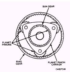
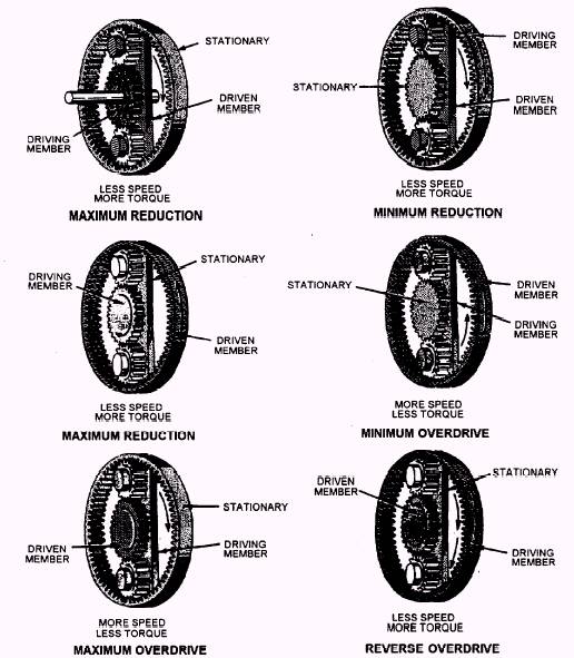
linkage to the range selector valve assembly on top of the transmission case. Movement of the gearshift lever positions the selector valve to allow main oil pressure to engage the desired clutch assembly. In modern power shift transmissions, the gearshift lever is connected to a range selector valve by hydraulic means. A spool valve (pilot control valve), actuated by the gearshift lever, directs main oil pressure to the range selector valve and causes it to direct main oil pressure to the desired clutch assembly. The hi-lo-shifting lever (on the transmission front cover) is held in position by a poppet lock in the hi-lo shifting housing. To shift from one range to another, the engine must be running and the gearshift lever must be in NEUTRAL position. This allows main oil pressure from the pump to pass through a drilled hole in the pilot valve and through an oil line to the shifter housing. Here it releases the poppet lock to enable shifting. Planetary Gearsets To cause a reduction or increase in torque, six different methods of connecting this gearset to the power train are possible (fig. 6-9). Direct drive is achieved by locking any two members together. and neutral is obtained by allowing all the gears to turn freely.
Figure 6-8.- Planetary gearset.
In figure 6-9 notice the direction of rotation as power is applied to the various members and others are stationary. In actual application, planetary gearsets are used as single or multiple units, depending on the number of speed (gear) ranges desired. On tracked equipment, power for turning the drive sprockets may flow through a planetary gear arrangement that provides maximum reduction (fig. 6-9). The sun gear forces the planetary gears to revolve in the stationary ring gear and move the carrier in the same direction of rotation as the sun gear. The carrier is connected to the hub on which the sprocket is mounted, causing it to rotate with the carrier. This arrangement produces the maximum torque and speed reduction obtainable from a planetary gearset. |
 |
|
|