Custom Search
|
|
  |
|
|
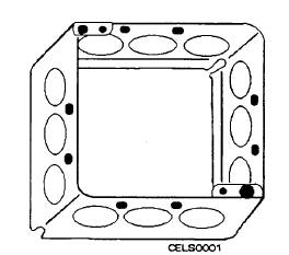
BOX SELECTION There is no firm requirement that a certain type of box be installed for a specific purpose. The usual practice is to install octagonal boxes for lighting outlets and to install rectangular and square boxes for switches and receptacle outlets. Round boxes are normally installed overhead for lighting purposes especially where the fixture canopy must cover the box. However, when the need arises because of inside space requirements, wall-surfacing materials used, number of electrical devices to be mounted, or the availability of boxes, almost any box can be used for any purpose. The size and number of conductors to be installed in a box have a definite impact on the selection of a box. Each conductor in a box must have some free air space to prevent a buildup of heat. As a result, the more conductors, or the larger their size, the bigger the box must be in which they are installed. The cubic inch capacity of a box is determined by its length, width, and depth. An increase in one or more of these dimensions increases box capacity. When gangable boxes are assembled together, box volume is the total of all sections assembled together. Also, when a raised cover or a box extension with volume markings is added to a box, as shown in figure 5-9, its capacity is added to the volume. The box to be mounted in each location is selected after the number and size of conductors it will contain
Figure 5-9.- Extension ring. are known In many cases, the usual box for the intended purpose is not adequate. To ensure proper air space for a conductor in a box, consult the table 370- 16( a) for metal boxes in the NEC(c). This table lists dimensions for common boxes, their cubic inch capacity, and the maximum permitted number of conductors in wire sizes No. 14 through No. 6. The number of conductors listed does not make allowance for fixture studs, cable clamps, grounding conductors, switches, or receptacles, or straps for mounting these devices. One conductor must be deducted from those listed when the box contains one or more fixture studs or cable clamps. Each strap containing one or more devices requires deduction of one conductor. Also, one conductor is deducted for one or more grounding conductors that enter the box. A conductor that runs through the box is counted as one conductor. Each conductor that terminates in the box counts as one. Fixture wires and conductors that do not leave the box, such as an internal grounding wire, are not counted. Let us use an example to see how the table works. Two receptacle outlets are to be installed using No. 12 nonmetallic cable. One of the outlets is to be installed as an extension to the other. Device boxes with cable clamps are to be used if possible. The first step is to determine the number of conductors that will be wired through the box. Two conductors plus a grounding conductor enter this box. Also, if a second outlet is to be connected to this one, then two conductors plus a grounding conductor must leave the box. If the preceding rules are followed, we have four conductors plus one for the grounding conductors, the equivalent of one conductor for the cable clamps, and the equivalent of one conductor for the receptacle outlet. This method gives us an equivalent of seven conductors. In looking at the table for metal boxes in the NEC(c), we do not find a listing given for seven No. 12 conductors in a device box. There are a couple of listings for eight conductors; one indicates a device box 3 by 2 by 3 1/ 2 inches is required. Since there will be an equivalent of just five conductors in the device box for the second outlet, the table shows a 3 by 2 by 2 1/ 2-inch box to be adequate. The table does not cover all the requirements for conductor space in boxes. Boxes of 100 cubic inches or less, not covered by the table, and nonmetallic boxes are marked with their cubic inch capacity. When these boxes are used or when conductors of different sizes are installed in the same box, the number of conductors allowed in a box is based on the free air space requirement for each conductor. The free air space needed is given in table 370-16( b) in the NEC(c). According to the table, the volume of space needed in cubic inches per conductor is 2 for No. 14, .2 1/ 4 for No. 12, 2 1/ 2 for No. 10, and so on. As an example, if a box is to contain four No. 10 conductors and two No. 12 conductors, multiply 4 times 2 1/ 2 and 2 times 2 1/ 4. This equals 14 1/ 2 cubic inches, the minimum sized box that can be installed.
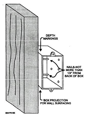
Figure 5-10.- Box installed with nails. Outlet and junction boxes are installed in a number of ways in either new construction or an old building. Article 370 of the NEC(c) gives the installation rules for outlet, switch, and junction boxes. In most cases, boxes in new construction are fastened with nails or screws. Usually, nails are preferred because they are cheaper and quicker to use. Unless the box has a bracket on it, the side of the box must be removed to use screws for mounting. Some of the newer box mounting brackets have prepunched and preformed devices that are driven into wood framing to support the box in the place of nails.
|
 |
|
|